Installation and Connections
Connection
|
|
| 1 |
|
|
| 2 |
(Pink/Black) AUDIO INTERRUPT IN |
| ||
(Blue/White) REMOTE | 3 | ||
| |||
(Red) | IGNITION | 4 |
|
(Black) | GND | 5 |
|
(Blue) | POWER ANT | 6 |
|
| 7 | 8 |
|
|
|
| |
(Yellow) | BATTERY |
| 9 |
|
| ||
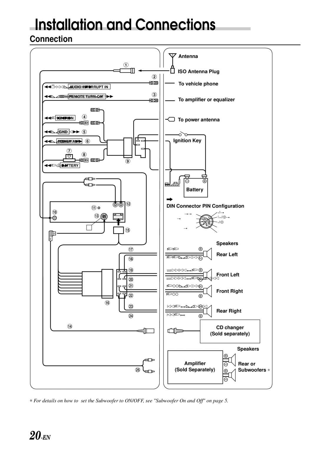
Antenna
ISO Antenna Plug
To vehicle phone
To amplifier or equalizer
To power antenna
Ignition Key
Battery
A
"
![]()
![]() #
#
DIN Connector PIN Configuration
!
$
A![]()
![]() &
&
lgnition | Shield Ground | |
Power Supply Ground | ||
Data Ground | ||
| ||
Lch | Battery | |
Sig Gnd | Data Bus | |
| ||
| Rch |
)
~
![]()
![]() +
+
![]()
![]()
![]()
![]() ,
,
![]()
![]()
![]()
![]() -
-
![]()
![]()
![]()
![]()
![]() .
.
(
/
:
Green
Green/Black
White
White/Black
Grey/Black
Grey
Violet/Black
Violet
Speakers
Rear Left
Front Left
Front Right
Rear Right
%
; |
CD changer
(Sold separately)
| Speakers |
Amplifier | Rear or |
(Sold Separately) | Subwoofers ∗ |
∗ For details on how to set the Subwoofer to ON/OFF, see "Subwoofer On and Off" on page 5.