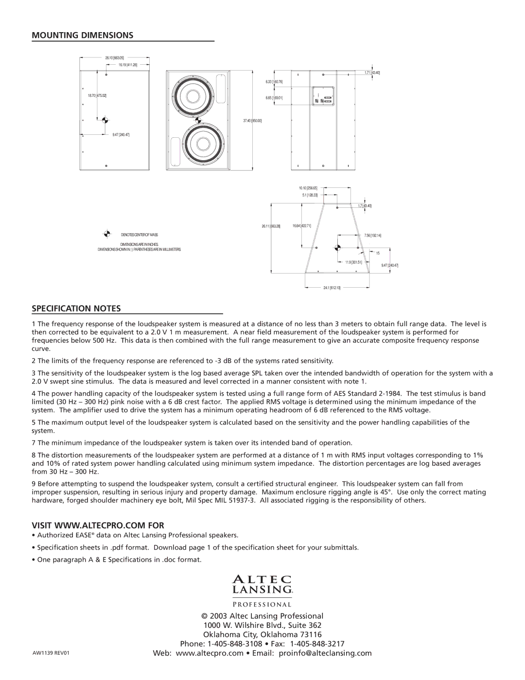
MOUNTING DIMENSIONS
26.10 [663.05]
16.19 [411.26]
18.70 [475.02]
9.47 [240.47]
DENOTES CENTER OF MASS
DIMENSIONS ARE IN INCHES.
DIMENSIONS SHOWN IN ( ) PARENTHESES ARE IN MILLIMETERS.
1.71 [43.40]
6.33 [160.76]
6.65 [169.01]
37.40 [950.00]
10.10 [256.65]
5.1 [128.33]
1.7 [43.40]
26.11 [663.28] | 16.64 [422.71] |
7.56 [192.14]
15
11.9 [301.51]
9.47 [240.47]
24.1 [612.10]
SPECIFICATION NOTES
1 The frequency response of the loudspeaker system is measured at a distance of no less than 3 meters to obtain full range data. The level is then corrected to be equivalent to a 2.0 V 1 m measurement. A near field measurement of the loudspeaker system is performed for frequencies below 500 Hz. This data is then combined with the full range measurement to give an accurate composite frequency response curve.
2 The limits of the frequency response are referenced to
3 The sensitivity of the loudspeaker system is the log based average SPL taken over the intended bandwidth of operation for the system with a 2.0 V swept sine stimulus. The data is measured and level corrected in a manner consistent with note 1.
4 The power handling capacity of the loudspeaker system is tested using a full range form of AES Standard
5 The maximum output level of the loudspeaker system is calculated based on the sensitivity and the power handling capabilities of the system.
7 The minimum impedance of the loudspeaker system is taken over its intended band of operation.
8 The distortion measurements of the loudspeaker system are performed at a distance of 1 m with RMS input voltages corresponding to 1% and 10% of rated system power handling calculated using minimum system impedance. The distortion percentages are log based averages from 30 Hz – 300 Hz.
9 Before attempting to suspend the loudspeaker system, consult a certified structural engineer. This loudspeaker system can fall from improper suspension, resulting in serious injury and property damage. Maximum enclosure rigging angle is 45°. Use only the correct mating hardware, forged shoulder machinery eye bolt, Mil Spec MIL
VISIT WWW.ALTECPRO.COM FOR
•Authorized EASE® data on Altec Lansing Professional speakers.
•Specification sheets in .pdf format. Download page 1 of the specification sheet for your submittals.
•One paragraph A & E Specifications in .doc format.
| P R OFE S S I ON A L |
| © 2003 Altec Lansing Professional |
| 1000 W. Wilshire Blvd., Suite 362 |
| Oklahoma City, Oklahoma 73116 |
| Phone: |
AW1139 REV01 | Web: www.altecpro.com • Email: proinfo@alteclansing.com |