DA1203RM specifications
The Altinex DA1203RM is a cutting-edge, high-performance video distribution amplifier designed to meet the demands of modern audio-visual systems. This reliable device is particularly well-suited for applications in conference rooms, classrooms, and large-scale installations where signal clarity and integrity are paramount.One of the standout features of the DA1203RM is its ability to support both analog and digital video formats, making it versatile for various setups. It accommodates signals from sources like DVD players, computers, and multimedia devices, facilitating seamless integration into existing AV infrastructures. Additionally, the amplifier can handle resolutions up to 1080p, ensuring high-definition signal transmission with minimal loss or distortion.
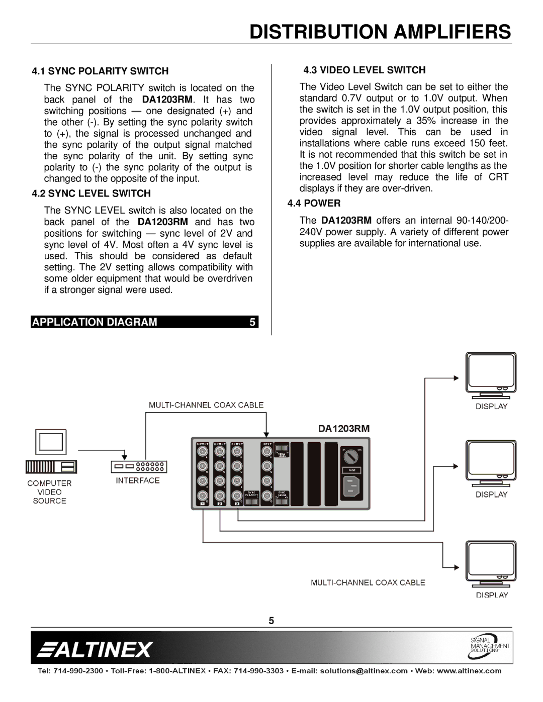
The DA1203RM boasts a robust input configuration, typically featuring a single input that can be duplicated across multiple output ports. This capability allows for the simultaneous distribution of one video signal to multiple displays or projectors, which is essential for presentations or large gathering environments. The device typically provides multiple output connections, including both VGA and HDMI, enabling users to connect to various types of display equipment.
In terms of technology, the Altinex DA1203RM employs advanced signal amplification techniques, ensuring that the video signals maintain their quality over longer distances. This is particularly important in installations where displays may be positioned far from the source. The built-in equalization feature adjusts the signal to compensate for distance, providing consistent performance throughout the installation.
Power management is another critical aspect of the DA1203RM, as it often features an efficient operating environment designed to minimize power consumption while maximizing output performance. Its compact design also contributes to space-saving solutions, making it easy to integrate into crowded racks or setups.
Furthermore, the DA1203RM is designed with user-friendly operation in mind. Many versions include manual and automatic switching capabilities, allowing for effortless input management. This means users can easily transition between different video sources, enhancing the audience experience during presentations or lectures.
Overall, the Altinex DA1203RM is an essential tool for anyone seeking reliable, high-quality video distribution in their audio-visual system. Its blend of advanced technology, versatile connectivity options, and user-centered design makes it a preferred choice for professionals in various fields.

