®
29" (73.7 cm) Gas Dryer
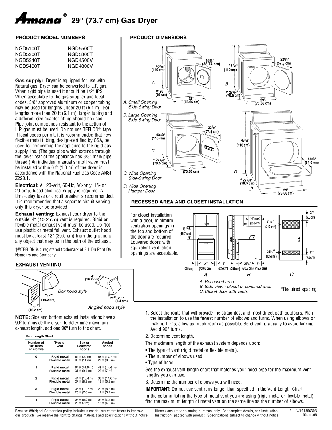
PRODUCT MODEL NUMBERS | PRODUCT DIMENSIONS |
| ||
NGD5100T | NGD5500T |
|
| |
NGD5200T | NGD5800T |
|
| |
NGD5240T | NGD4500V |
|
| |
NGD5400T | NGD4800V |
|
| |
Gas supply: Dryer is equipped for use with | A | B | ||
Natural gas. Dryer can be converted to L.P. gas. | ||||
|
| |||
When rigid pipe is used it should be 1/2" IPS. |
|
| ||
When acceptable to the gas supplier and local |
|
| ||
codes, 3/8" approved aluminum or copper tubing | A. Small Opening |
| ||
may be used for lengths under 20 ft (6.1 m). For |
| |||
lengths more than 20 ft (6.1 m), larger tubing and | B. Large Opening |
| ||
a different size adapter fitting should be used. |
| |||
| ||||
|
|
| ||
L.P. gas must be used. Do not use TEFLON®† tape. |
|
| ||
If local codes permit, it is recommended that new |
|
| ||
flexible metal tubing, |
|
| ||
used for connecting the appliance to the rigid gas |
|
| ||
supply line. (The gas pipe which extends through | C |
| ||
the lower rear of the appliance has 3/8" male pipe |
|
| ||
thread.) An individual manual shutoff valve must |
|
| ||
be installed within 6 ft (1.8 m) of the dryer in |
| D | ||
accordance with the National Fuel Gas Code ANSI | C. Wide Opening | |||
Z223.1. |
|
| ||
Electrical: A | D. Wide Opening |
| ||
Hamper Door |
| |||
|
| |||
It is recommended that a separate circuit serving | RECESSED AREA AND CLOSET INSTALLATION | |||
only this dryer be provided. |
|
| ||
Exhaust venting: Exhaust your dryer to the | For closet installation |
|
|
|
|
|
|
|
|
| 3"* |
|
|
|
| 14"max.* |
|
|
| (7.6 cm) | |||
outside. 4" (10.2 cm) vent is required. Rigid or | with a door, minimum |
|
|
|
|
|
|
| |||
|
|
|
| 48 in. | 2 | * |
| ||||
|
|
|
| (35.6cm) |
| ||||||
flexible metal exhaust vent must be used. Do Not | ventilation openings in |
|
|
|
|
|
| ||||
18"* |
|
|
|
|
| (310 cm2 ) |
| ||||
use plastic or metal foil vent. Exhaust outlet hood | the top and bottom of |
|
|
|
|
|
|
|
|
| |
(45.7 cm) |
|
|
|
|
|
|
|
|
| ||
must be at least 12" (30.5 cm) from the ground or | the door are required. |
|
|
|
|
|
|
|
|
| |
|
|
|
|
|
|
|
|
|
| ||
any object that may be in the path of the exhaust. | Louvered doors with |
|
|
|
|
|
|
|
|
|
|
†®TEFLON is a registered trademark of E.I. Du Pont De | equivalent ventilation |
|
|
|
|
|
|
| 2 | * |
|
openings are acceptable. |
|
|
|
|
|
|
|
| |||
Nemours and Company. |
|
|
|
|
|
| 24 in. | 2 | 3"* | ||
|
|
|
|
|
|
| (155 cm ) | (7.6 cm) | |||
|
|
|
|
|
|
|
| ||||
EXHAUST VENTING |
| 1" | 29" | 1" | 1"* | 27¾" | 5"* |
|
|
|
|
|
| (2.5 cm) | (73.66 cm) | (2.5 cm) | (2.5 cm) | (70.5 cm) | (12.7 cm) |
|
|
| |
4" |
|
| A |
|
| B |
|
|
|
| C |
(10.2 cm) |
|
| A. Recessed area |
|
|
|
|
|
| ||
|
|
|
|
|
|
|
|
| |||
Box hood style |
|
| B. Side view - closet or confined area |
|
| *Required spacing | |||||
|
| C. Closet door with vents |
|
|
|
| |||||
|
|
|
|
|
|
| |||||
4" | 2.5" |
|
|
|
|
|
|
|
|
|
|
(10.2 cm) |
|
|
|
|
|
|
|
|
|
| |
(6.4 cm) |
|
|
|
|
|
|
|
|
|
| |
|
|
|
|
|
|
|
|
|
|
| |
|
| 4" |
| Angled hood style |
| ||||
| (10.2 cm) |
|
|
|
| 1. Select the route that will provide the straightest and most direct path outdoors. Plan | |||
NOTE: Side and bottom exhaust installations have a | |||||||||
the installation to use the fewest number of elbows and turns. When using elbows or | |||||||||
90º turn inside the dryer. To determine maximum | making turns, allow as much room as possible. Bend vent gradually to avoid kinking. | ||||||||
exhaust length, add one 90º turn to the chart. | Avoid 90° turns. | ||||||||
| Vent Length Chart |
|
|
| 2. Determine vent length. | ||||
| Number of | Type of | Box or | Angled | The maximum length of the exhaust system depends upon: | ||||
| 90° turns | vent | Louvered | hoods | • The type of vent (rigid metal or flexible metal). | ||||
| or elbows |
| hoods |
|
| ||||
|
|
|
|
|
|
|
| ||
0 | Rigid metal | 64 ft (20 m) | 58 ft (17.7 m) | • The number of elbows used. | |||||
|
|
|
| Flexible metal | 36 ft (11 m) | 28 ft (8.5 m) | • Type of hood. | ||
|
|
|
|
|
|
|
| ||
1 | Rigid metal | 54 ft (16.5 m) | 48 ft (14.6 m) | See the exhaust vent length chart that matches your hood type for the maximum vent | |||||
|
|
|
| Flexible metal | 31 ft (9.4 m) | 23 ft (7 m) | |||
|
|
|
|
|
|
|
| lengths you can use. | |
2 | Rigid metal | 44 ft (13.4 m) | 38 ft (11.6 m) | ||||||
3. Determine the number of elbows you will need. | |||||||||
|
|
|
| Flexible metal | 27 ft (8.2 m) | 19 ft (5.8 m) | |||
|
|
|
|
|
|
|
| IMPORTANT: Do not use vent runs longer than specified in the Vent Length Chart. | |
3 | Rigid metal | 35 ft (10.7 m) | 29 ft (8.8 m) | ||||||
|
|
|
| Flexible metal | 25 ft (7.6 m) | 17 ft (5.2 m) | In the column listing the type of metal vent you are using (rigid metal or flexible metal), | ||
|
|
|
|
|
|
|
| ||
4 | Rigid metal | 27 ft (8.2 m) | 21 ft (6.4 m) | ||||||
find the maximum length of metal vent on the same line as the number of elbows. | |||||||||
|
|
|
| Flexible metal | 23 ft (7 m) | 15 ft (4.6 m) | |||
Because Whirlpool Corporation policy includes a continuous commitment to improve our products, we reserve the right to change materials and specifications without notice.
Dimensions are for planning purposes only. For complete details, see Installation | Ref. W10150630B |
Instructions packed with product. Specifications subject to change without notice. |