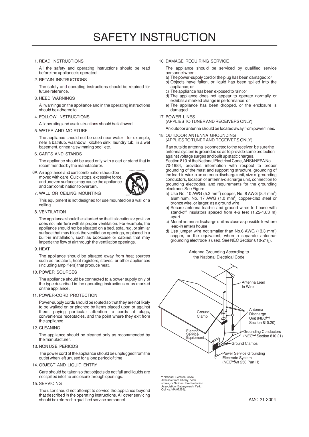
SAFETY INSTRUCTION

1.READ INSTRUCTIONS

All the safety and operating instructions should be read before the appliance is operated.

2.RETAIN INSTRUCTIONS

The safety and operating instructions should be retained for future reference.

3.HEED WARNINGS

All warnings on the appliance and in the operating instructions should be adhered to.

4.FOLLOW INSTRUCTIONS

All operating and use instructions should be followed.

5.WATER AND MOISTURE

The appliance should not be used near water - for example, near a bathtub, washbowl, kitchen sink, laundry tub, in a wet basement, or near a swimming pool, etc.

6.CARTS AND STANDS

The appliance should be used only with a cart or stand that is recommended by the manufacturer.

16. DAMAGE REQUIRING SERVICE

The appliance should be serviced by qualified service

personnel when:

a) The power-supply cord or the plug has been damaged; or

b) Objects have fallen, or liquid has been spilled into the

appliance; or

c) The appliance has been exposed to rain; or

d) The appliance does not appear to operate normally or

exhibits a marked change in performance; or

e) The appliance has been dropped, or the enclosure is

damaged.

17. POWER LINES

(APPLIES TO TUNER AND RECEIVERS ONLY)

An outdoor antenna should be located away from power lines.

18. OUTDOOR ANTENNA GROUNDING

(APPLIES TO TUNER AND RECEIVERS ONLY)

If an outside antenna is connected to the receiver, be sure the

antenna system is grounded so as to provide some protection

against voltage surges and built up static charges.

Section 810 of the National Electrical Code, ANSI/NFPA No.

70-1984, provides information with respect to proper

grounding of the mast and supporting structure, grounding of

6A.An appliance and cart combination should be moved with care. Quick stops, excessive force, and uneven surfaces may cause the appliance and cart combination to overturn.

PORTABLE CART WARNING

the lead-in wire to an antenna discharge unit, size of grounding

conductors, location of antenna-discharge unit, connection to

grounding electrodes, and requirements for the grounding

electrode. See Figure.

7. WALL OR CEILING MOUNTING

S3125A

This equipment is not designed for use mounted on a wall or a ceiling.

8.VENTILATION

The appliance should be situated so that its location or position does not interfere with its proper ventilation. For example, the appliance should not be situated on a bed, sofa, rug, or similar surface that may block the ventilation openings, or placed in a built-in installation, such as bookcase or cabinet that may impede the flow of air through the ventilation openings.

9.HEAT

The appliance should be situated away from heat sources such as radiators, heat registers, stoves, or other appliances (including amplifiers) that produce heat.

10.POWER SOURCES

The appliance should be connected to a power supply only of the type described in the operating instructions or as marked on the appliance.

11.POWER-CORD PROTECTION

Power-supply cords should be routed so that they are not likely to be walked on or pinched by items placed upon or against them, paying particular attention to cords at plugs, convenience receptacles, and the point where they exit from the appliance

12.CLEANING

The appliance should be cleaned only as recommended by the manufacturer.

13.NON USE PERIODS

The power cord of the appliance should be unplugged from the outlet when left unused for a long period of time.

14.OBJECT AND LIQUID ENTRY

Care should be taken so that objects do not fall and liquids are not spilled into the enclosure through openings.

15.SERVICING

The user should not attempt to service the appliance beyond that described in the operating instructions. All other servicing should be referred to qualified service personnel.

a) Use No. 10 AWG (5.3 mm2) copper, No. 8 AWG (8.4 mm2)

aluminum, No. 17 AWG (1.0 mm2) copper-clad steel or

bronze wire, or larger, as a ground wire.

b) Secure antenna lead-in and ground wires to house with

stand-off insulators spaced from 4-6 feet (1.22-1.83 m)

apart.

c) Mount antenna discharge unit as close as possible to where

lead-in enters house.

d) Use jumper wire not smaller than No.6 AWG (13.3 mm2)

copper, or the equivalent, when a separate antenna-

grounding electrode is used. See NEC Section 810-21(j).

Antenna Grounding According to

the National Electrical Code


Antenna Lead


In Wire

Ground

Antenna

Discharge

Clamp

Unit (NEC


Section 810.20)

Electric

Grounding Conductors

Service

(NEC Section 810.21)

Equipment


Ground Clamps

Power Service Grounding

Electrode System

(NEC Art 250 Part H)

National Electrical Code

Available from Library, book

stores, or National Fire Protection

Association (Batterymarch Park,

Quincy. MA 02269).

AMC 21-3004

Page 18
Image 18
AMC TR1a manual Safety Instruction

TR1a specifications

The AMC TR1a is an advanced multi-role military vehicle designed for versatility and performance in various operational environments. As part of the AMC family of vehicles, the TR1a stands out due to its unique combination of mobility, advanced technology, and robust design.

One of the main features of the AMC TR1a is its exceptional off-road capability. Equipped with a powerful all-wheel-drive system, it can traverse challenging terrains, ensuring that it can operate effectively across diverse landscapes, from rugged mountains to sandy deserts. The TR1a's chassis is designed to withstand rigorous conditions, featuring reinforced materials and a high ground clearance that allows it to navigate obstacles with ease.

The vehicle is powered by a state-of-the-art engine that provides optimal horsepower and torque, enabling rapid acceleration and high-speed travel. This powertrain is coupled with an automatic transmission system that enhances driving performance and simplifies operation for crew members. Furthermore, the TR1a incorporates an advanced suspension system that improves ride comfort and handling, reducing fatigue on long missions.

In terms of technology, the AMC TR1a is equipped with an advanced battlefield management system that integrates communication, navigation, and reconnaissance capabilities. This system ensures that operators have real-time situational awareness, allowing for informed decision-making during missions. The vehicle supports various communication protocols, enabling secure and effective coordination with other units on the field.

The AMC TR1a also emphasizes protection for its crew and cargo. It features an integrated armor system designed to withstand ballistic threats and improvised explosive devices (IEDs). The vehicle’s design prioritizes crew safety, with strategically placed armor and blast-resistant compartments that mitigate risks during operations.

Moreover, the TR1a exhibits modularity, allowing for easy adaptation to various mission requirements. It can be configured for different roles, such as troop transport, medical evacuation, or command and control operations, enhancing its usability across military branches.

Overall, the AMC TR1a represents a significant advancement in military vehicle technology, combining outstanding mobility, advanced systems, and robust protection in a single platform. Its versatility positions it as a critical asset in any modern military's operational arsenal, capable of addressing diverse challenges on the battlefield.