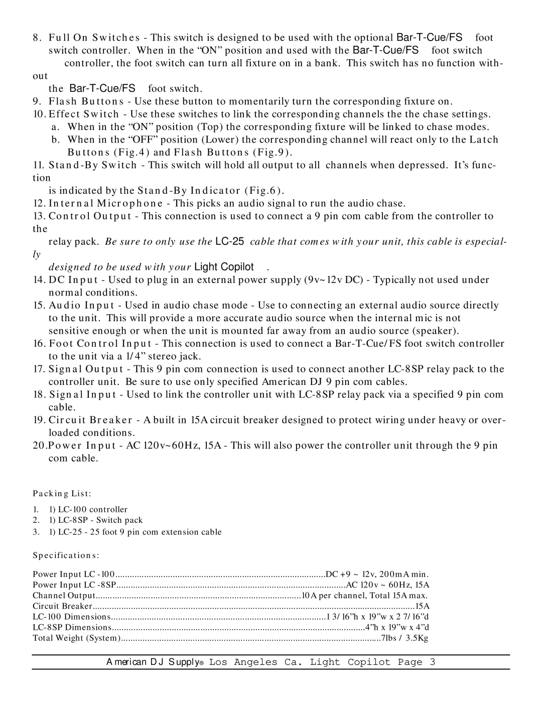
Light Copilot specifications
The American DJ Light Copilot is a groundbreaking tool designed for DJs and lighting professionals seeking to elevate their performances through innovative light control. This powerful device offers a range of features and technologies that streamline the process of lighting design, enhancing both the creativity and efficiency of live shows.One of the standout features of the Light Copilot is its intuitive interface, which allows users to easily control and customize their lighting setup. With a built-in touchscreen display, navigating through various options and settings becomes a breeze. The user-friendly design enables DJs to focus on their performance without being bogged down by complicated controls.
The Light Copilot supports DMX devices, making it compatible with a vast array of lighting fixtures. This compatibility provides flexibility for users to incorporate different types of lights, whether they are LED par cans, moving heads, or laser devices. The device features a robust DMX output, allowing for precise control over multiple channels and fixtures, ensuring that every light responds exactly as intended.
Another significant aspect of the American DJ Light Copilot is its first-rate programming capabilities. The device includes thousands of pre-built effects and light shows that can be easily adjusted and triggered during performances. This feature allows DJs to create dynamic and engaging light displays without needing extensive programming expertise.
Moreover, the Light Copilot is equipped with advanced automation features. This includes the ability to sync lighting effects with music beats, creating a visually immersive experience that compliments audio elements. The music analysis technology built into the device listens to the beats and cues, allowing the lights to dance in synchronization with the music, thus heightening the ambiance for the audience.
Portability is another highlight of the Light Copilot. Its compact design makes it easy to transport to different venues, making it an ideal choice for mobile DJs and performers. The device is also built with durability in mind, ensuring it can withstand the rigors of frequent use in diverse environments.
In conclusion, the American DJ Light Copilot stands out in the competitive world of lighting control for DJs. With its user-friendly interface, robust DMX compatibility, powerful programming capabilities, and innovative automation features, it represents a significant advancement in live performance lighting technology. This makes it a valuable asset for any DJ looking to enhance their shows and create unforgettable experiences for their audience.