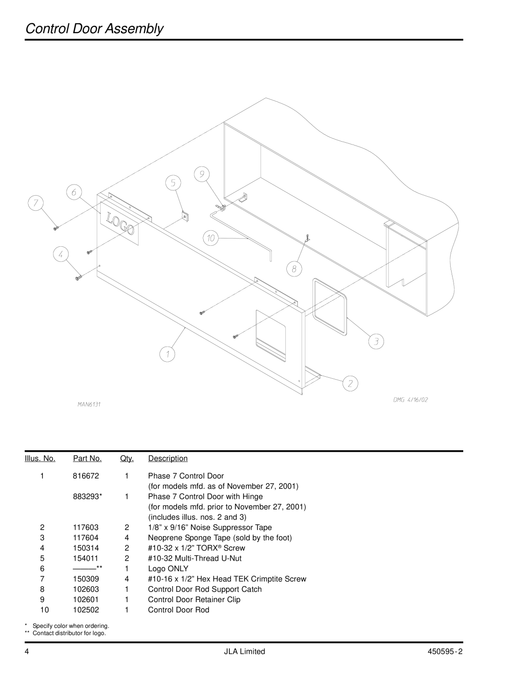
D90 specifications
The American Dryer Corporation D90 is a state-of-the-art commercial clothes dryer designed for efficiency, reliability, and user-friendly operation. This model stands out in the market for its robust construction and advanced features that cater to the demands of high-usage environments such as laundromats, hotels, and athletic facilities.One of the main features of the D90 is its impressive drying capacity. With a large drum capable of handling up to 90 pounds of laundry per cycle, it significantly reduces drying times and improves overall productivity. This spacious design accommodates bulky items such as bedding and towels, allowing businesses to maximize their drying operations.
Equipped with a powerful, energy-efficient heating system, the D90 ensures optimal drying performance. The advanced heating technology not only accelerates the drying process but also helps to lower energy consumption, making it an eco-friendly option for commercial laundries. Additionally, the dryer features an intuitive control panel that includes user-friendly digital displays and programmable settings, enabling users to tailor the drying process to their specific laundry needs.
Another notable characteristic of the D90 is its multi-cycle programming. This feature allows operators to choose from a variety of drying cycles, ensuring that different types of fabrics receive the appropriate treatment. Whether the load consists of delicate garments or heavy-duty items, the D90 can handle it all with precision.
The D90 also boasts a durable design, constructed with high-quality materials to withstand the rigors of commercial use. Its robust framework and reinforced drum enhance longevity, thus providing a reliable solution for businesses in need of consistent performance over time.
In terms of safety, the D90 includes critical features such as an automatic shut-off system that activates when the door is opened during operation, preventing accidents and ensuring user safety. Additionally, built-in lint screens make maintenance straightforward and help maintain operational efficiency.
In summary, the American Dryer Corporation D90 is a premier commercial drying solution that combines high-capacity performance, energy efficiency, and user-friendly features. Its innovative technology and durable construction make it a top choice for businesses focused on providing quality laundry services while optimizing operational efficiency. Whether drying large loads of laundry or specialized fabric blends, the D90 is designed to meet the demands of any commercial laundry environment.

