Burner Control Panel Assembly | 15 |
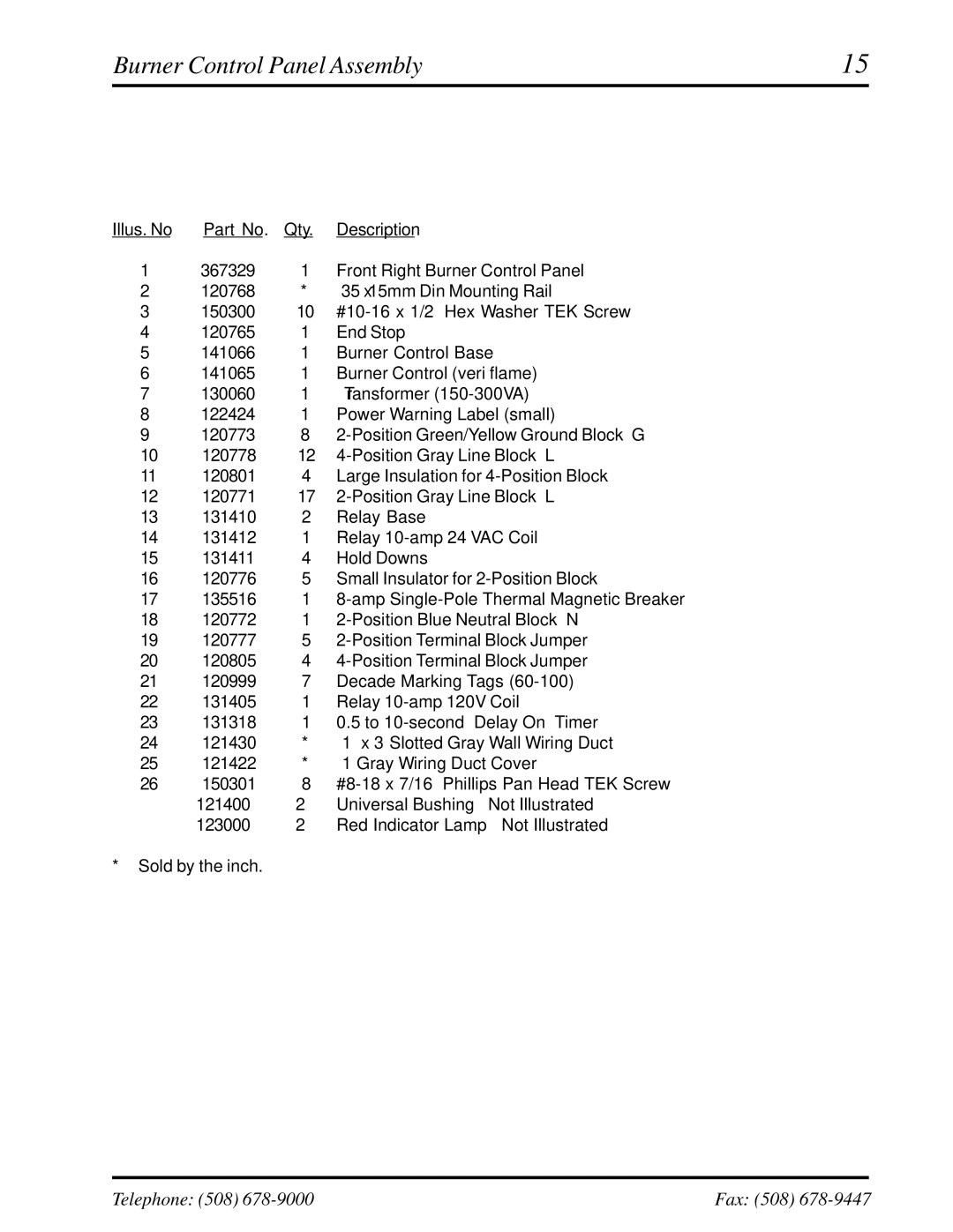
Illus. No | Part No. | Qty. | Description |
1 | 367329 | 1 | Front Right Burner Control Panel |
2 | 120768 | * | 35 x 15mm Din Mounting Rail |
3 | 150300 | 10 | |
4 | 120765 | 1 | End Stop |
5 | 141066 | 1 | Burner Control Base |
6 | 141065 | 1 | Burner Control (veri flame) |
7 | 130060 | 1 | Transformer |
8 | 122424 | 1 | Power Warning Label (small) |
9 | 120773 | 8 | |
10 | 120778 | 12 | |
11 | 120801 | 4 | Large Insulation for |
12 | 120771 | 17 | |
13 | 131410 | 2 | Relay Base |
14 | 131412 | 1 | Relay |
15 | 131411 | 4 | Hold Downs |
16 | 120776 | 5 | Small Insulator for |
17 | 135516 | 1 | |
18 | 120772 | 1 | |
19 | 120777 | 5 | |
20 | 120805 | 4 | |
21 | 120999 | 7 | Decade Marking Tags |
22 | 131405 | 1 | Relay |
23 | 131318 | 1 | 0.5 to |
24 | 121430 | * | 1” x 3” Slotted Gray Wall Wiring Duct |
25 | 121422 | * | 1” Gray Wiring Duct Cover |
26 | 150301 | 8 | |
– | 121400 | 2 | Universal Bushing – Not Illustrated |
– | 123000 | 2 | Red Indicator Lamp – Not Illustrated |
*Sold by the inch.
Telephone: (508) | Fax: (508) |
