®

Back-UPS

CS

325I/475I

User’s Manual

990-2114 8/01

Installation

1


Placement / Power

2 Connect Equipment

3 Switch on the

Avoid placing the Back-UPS in:

to the Back-UPS

Back-UPS


Direct sunlight

The rear panel of the Back-UPS consists of the

Note: Allow the Back-UPS to charge for a full eight

Excessive heat

following elements:

hours prior to use.


Press the push-button on Back-UPS front panel.

Excessive humidity or in contact with fluids

Battery Back Up Outlets (qty. of 3). These


of any type

outlets provide battery back-up, surge protection,


and Electro-magnetic Interference (EMI) filtering.


In case of power outage, battery power is


automatically provided to these outlets. Power


ON LINE


(utility or battery) is not supplied to these outlets


when the Back-UPS is switched Off. Connect a


ON BATTERY


computer, monitor, and external disk or CD-ROM


drive to these outlets.


OVERLOAD


Surge Only Outlet. This outlet is always On


REPLACE BATTERY


Plug the Back-UPS into a wall outlet, as shown.


(when utility power is available) and is not


controlled by the On/Off switch. This outlet does


not provide power during a power outage. Connect


a printer, fax machine or scanner to this outlet.


Observe that the following events occur after pressing


and releasing the push-button:


• The green On-Lineindicator flashes.


• The yellow On Battery indicator lights while the


Self-Testis being performed.


• When Self-Testhas successfully completed, only


Your computer’s power cord.


the green On Line indicator will be lit.


• If the internal battery is not connected, (see Step 1


above) the green On Line indicator and red


The Back-UPS charges the internal battery


Replace Battery indicator will light. The Back-


any time it is connected to a wall outlet.


UPS will also emit a chirping sound.


Status Indicators and Alarms


Replace the Internal Battery


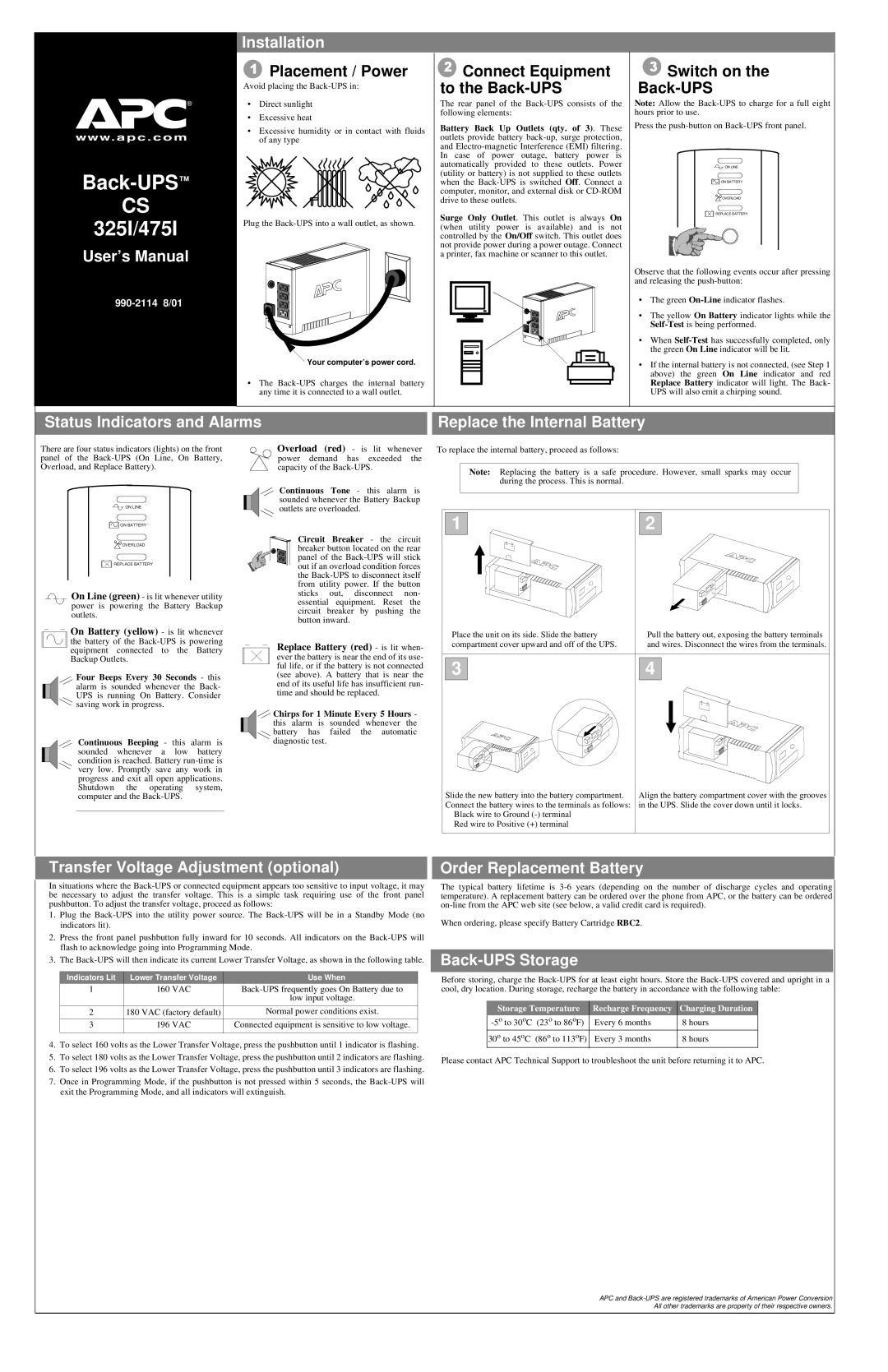
There are four status indicators (lights) on the front panel of the Back-UPS (On Line, On Battery, Overload, and Replace Battery).

ON LINE

Overload (red) - is lit whenever power demand has exceeded the capacity of the Back-UPS.

Continuous Tone - this alarm is sounded whenever the Battery Backup outlets are overloaded.

To replace the internal battery, proceed as follows:

Note: Replacing the battery is a safe procedure. However, small sparks may occur during the process. This is normal.

ON BATTERY

OVERLOAD

REPLACE BATTERY

On Line (green) - is lit whenever utility power is powering the Battery Backup outlets.

On Battery (yellow) - is lit whenever

the battery of the Back-UPS is powering equipment connected to the Battery Backup Outlets.

Four Beeps Every 30 Seconds - this alarm is sounded whenever the Back- UPS is running On Battery. Consider saving work in progress.

Circuit Breaker - the circuit breaker button located on the rear panel of the Back-UPS will stick out if an overload condition forces the Back-UPS to disconnect itself from utility power. If the button sticks out, disconnect non- essential equipment. Reset the circuit breaker by pushing the button inward.

Replace Battery (red) - is lit when- ever the battery is near the end of its use- ful life, or if the battery is not connected (see above). A battery that is near the end of its useful life has insufficient run- time and should be replaced.

Chirps for 1 Minute Every 5 Hours - this alarm is sounded whenever the battery has failed the automatic

1

Place the unit on its side. Slide the battery compartment cover upward and off of the UPS.

3

2

Pull the battery out, exposing the battery terminals and wires. Disconnect the wires from the terminals.

4

Continuous Beeping - this alarm is sounded whenever a low battery condition is reached. Battery run-time is very low. Promptly save any work in progress and exit all open applications. Shutdown the operating system, computer and the Back-UPS.

diagnostic test.

Slide the new battery into the battery compartment.

Align the battery compartment cover with the grooves

Connect the battery wires to the terminals as follows:

in the UPS. Slide the cover down until it locks.

Black wire to Ground (-) terminal


Red wire to Positive (+) terminal


Transfer Voltage Adjustment (optional)

In situations where the Back-UPS or connected equipment appears too sensitive to input voltage, it may be necessary to adjust the transfer voltage. This is a simple task requiring use of the front panel pushbutton. To adjust the transfer voltage, proceed as follows:

1.Plug the Back-UPS into the utility power source. The Back-UPS will be in a Standby Mode (no indicators lit).

2.Press the front panel pushbutton fully inward for 10 seconds. All indicators on the Back-UPS will flash to acknowledge going into Programming Mode.

3.The Back-UPS will then indicate its current Lower Transfer Voltage, as shown in the following table.

Indicators Lit

Lower Transfer Voltage

Use When

1

160 VAC

Back-UPS frequently goes On Battery due to


low input voltage.

2

180 VAC (factory default)

Normal power conditions exist.

3

196 VAC

Connected equipment is sensitive to low voltage.


4.To select 160 volts as the Lower Transfer Voltage, press the pushbutton until 1 indicator is flashing.

5.To select 180 volts as the Lower Transfer Voltage, press the pushbutton until 2 indicators are flashing.

6.To select 196 volts as the Lower Transfer Voltage, press the pushbutton until 3 indicators are flashing.

7.Once in Programming Mode, if the pushbutton is not pressed within 5 seconds, the Back-UPS will exit the Programming Mode, and all indicators will extinguish.

Order Replacement Battery

The typical battery lifetime is 3-6 years (depending on the number of discharge cycles and operating temperature). A replacement battery can be ordered over the phone from APC, or the battery can be ordered on-line from the APC web site (see below, a valid credit card is required).

When ordering, please specify Battery Cartridge RBC2.

Back-UPS Storage

Before storing, charge the Back-UPS for at least eight hours. Store the Back-UPS covered and upright in a cool, dry location. During storage, recharge the battery in accordance with the following table:

Storage Temperature

Recharge Frequency

Charging Duration

-5oto 30oC (23o to 86oF)

Every 6 months

8 hours

30o to 45oC (86o to 113oF)

Every 3 months

8 hours

Please contact APC Technical Support to troubleshoot the unit before returning it to APC.

APC and Back-UPS are registered trademarks of American Power Conversion All other trademarks are property of their respective owners.

Page 1
Image 1
American Power Conversion 325I, 475I user manual User’s Manual, Installation, Transfer Voltage Adjustment optional

325I, 475I specifications

American Power Conversion (APC) has long been synonymous with reliable power management solutions. Among its notable offerings are the APC 325I and 475I models, designed to cater to the demanding needs of data centers, IT infrastructures, and critical installations. Both models represent APC's commitment to excellence, integrating advanced technologies that ensure superior performance and energy efficiency.

The APC 325I is a robust unit that delivers an output power of 325 VA, making it especially suitable for small to medium-sized installations. It is equipped with advanced features such as automatic voltage regulation (AVR), which stabilizes the output voltage, enhancing the longevity of attached equipment. The user-friendly LCD interface provides real-time status updates, allowing users to monitor vital metrics such as battery health, load levels, and input/output voltage. This level of visibility empowers users to make informed decisions about maintenance and operational adjustments.

On the other hand, the APC 475I offers a higher output capacity of 475 VA, making it ideal for larger setups where power demands are greater. One of its notable characteristics is its seamless integration capabilities with existing infrastructure. The model supports hot-swappable batteries, which allow for uninterrupted operation during maintenance periods. This feature is critical for environments where uptime is paramount, such as data centers and healthcare facilities.

Both models incorporate advanced battery technology, providing extended runtime to ensure that your critical devices remain powered during outages. APC's intelligent battery management system optimizes charge cycles, thus prolonging battery life and enhancing overall reliability. Furthermore, the units feature an energy-efficient design that minimizes operating costs while maximizing performance.

In addition to their technical specifications, the APC 325I and 475I prioritize safety with multiple layers of protection against overloads, surges, and short circuits. These protections ensure that critical devices are shielded from potential damages caused by power variations.

In summary, the APC 325I and 475I are exemplary power solutions characterized by their durability, efficiency, and user-centric design. With features such as AVR, intelligent battery management, and robust safety protocols, these models not only cater to today's power needs but also pave the way for future advancements in power management technology. For organizations striving for operational continuity and reliability, investing in APC's power systems is a strategic choice.