Back-UPS® ES 400/550/700
User’s Guide
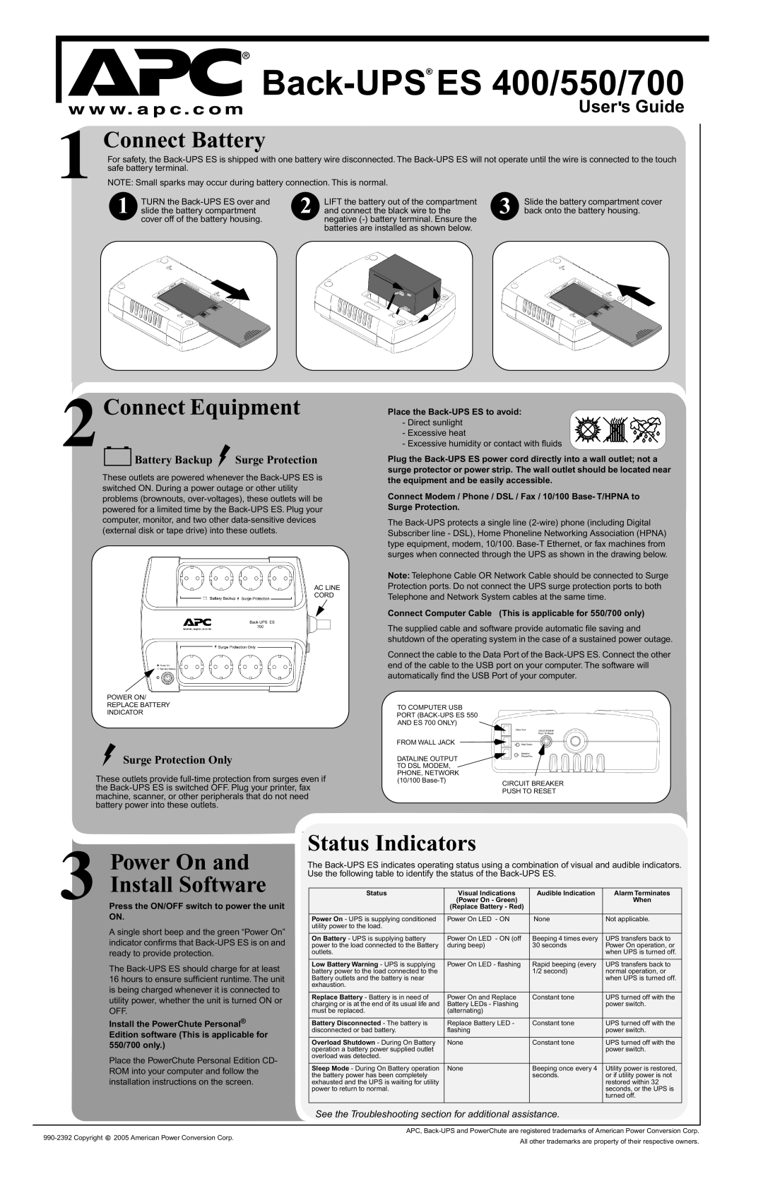
1 Connect Battery
For safety, the
NOTE: Small sparks may occur during battery connection. This is normal.
1 | TURN the |
slide the battery compartment |
cover off of the battery housing.
2 | LIFT the battery out of the compartment | 3 | Slide the battery compartment cover |
and connect the black wire to the | back onto the battery housing. |
negative
2 Connect Equipment
Battery Backup Surge Protection
These outlets are powered whenever the
Place the
- Direct sunlight
-Excessive heat
-Excessive humidity or contact with fluids
Plug the
problems (brownouts,
AC LINE
CORD
POWER ON/
REPLACE BATTERY
INDICATOR
Surge Protection Only
These outlets provide
Connect Modem / Phone / DSL / Fax / 10/100 Base- T/HPNA to Surge Protection.
The
Note: Telephone Cable OR Network Cable should be connected to Surge Protection ports. Do not connect the UPS surge protection ports to both Telephone and Network System cables at the same time.
Connect Computer Cable (This is applicable for 550/700 only)
The supplied cable and software provide automatic file saving and shutdown of the operating system in the case of a sustained power outage.
Connect the cable to the Data Port of the
TO COMPUTER USB
PORT
AND ES 700 ONLY)
FROM WALL JACK
DATALINE OUTPUT TO DSL MODEM,
PHONE, NETWORK
(10/100
3 Power On and Install Software
Press the ON/OFF switch to power the unit ON.
A single short beep and the green “Power On” indicator confirms that
The
Install the PowerChute Personal® Edition software (This is applicable for 550/700 only.)
Place the PowerChute Personal Edition CD- ROM into your computer and follow the installation instructions on the screen.
Status Indicators
The
Status | Visual Indications | Audible Indication | Alarm Terminates |
| (Power On - Green) |
| When |
| (Replace Battery - Red) |
|
|
|
|
|
|
Power On - UPS is supplying conditioned | Power On LED - ON | None | Not applicable. |
utility power to the load. |
|
|
|
|
|
|
|
On Battery - UPS is supplying battery | Power On LED - ON (off | Beeping 4 times every | UPS transfers back to |
power to the load connected to the Battery | during beep) | 30 seconds | Power On operation, or |
outlets. |
|
| when UPS is turned off. |
|
|
|
|
Low Battery Warning - UPS is supplying | Power On LED - flashing | Rapid beeping (every | UPS transfers back to |
battery power to the load connected to the |
| 1/2 second) | normal operation, or |
Battery outlets and the battery is near |
|
| when UPS is turned off. |
exhaustion. |
|
|
|
|
|
|
|
Replace Battery - Battery is in need of | Power On and Replace | Constant tone | UPS turned off with the |
charging or is at the end of its usual life and | Battery LEDs - Flashing |
| power switch. |
must be replaced. | (alternating) |
|
|
|
|
|
|
Battery Disconnected - The battery is | Replace Battery LED - | Constant tone | UPS turned off with the |
disconnected or bad battery. | flashing |
| power switch. |
|
|
|
|
Overload Shutdown - During On Battery | None | Constant tone | UPS turned off with the |
operation a battery power supplied outlet |
|
| power switch. |
overload was detected. |
|
|
|
|
|
|
|
Sleep Mode - During On Battery operation | None | Beeping once every 4 | Utility power is restored, |
the battery power has been completely |
| seconds. | or if utility power is not |
exhausted and the UPS is waiting for utility |
|
| restored within 32 |
power to return to normal. |
|
| seconds, or the UPS is |
|
|
| turned off. |
|
|
|
|
See the Troubleshooting section for additional assistance.
2005 American Power Conversion Corp. | APC, | ||
All other trademarks are property of their respective owners. | |||
|
|