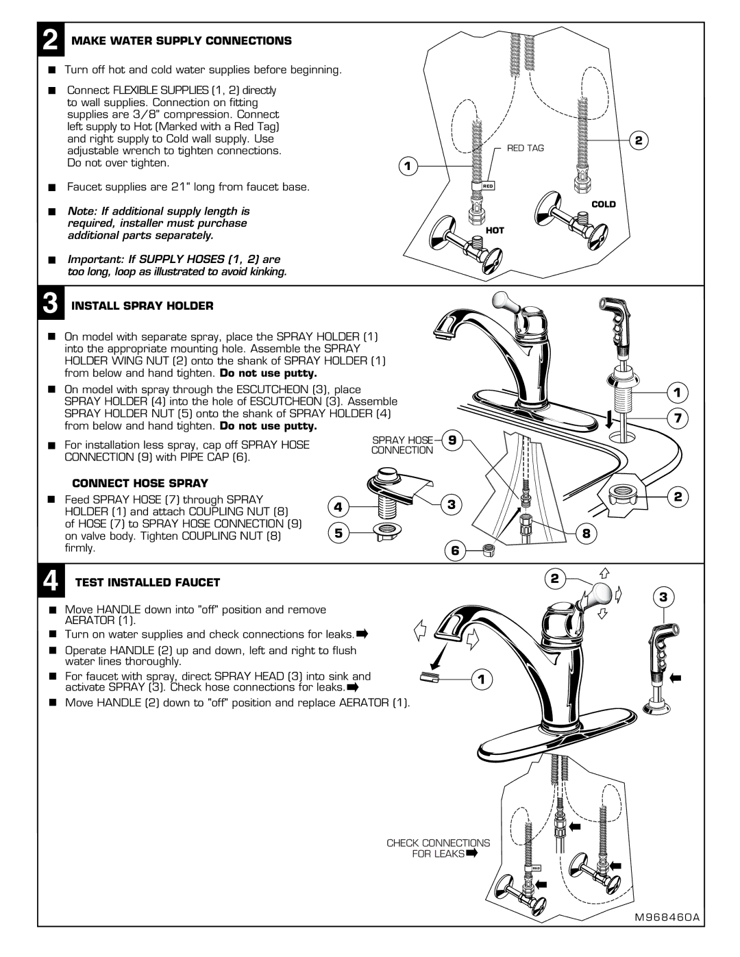
2 MAKE WATER SUPPLY CONNECTIONS |
| |
Turn off hot and cold water supplies before beginning. |
| |
Connect FLEXIBLE SUPPLIES (1, 2) directly |
| |
to wall supplies. Connection on fitting |
| |
supplies are 3/8" compression. Connect |
| |
left supply to Hot (Marked with a Red Tag) |
| |
and right supply to Cold wall supply. Use | 2 | |
adjustable wrench to tighten connections. | RED TAG | |
Do not over tighten. | 1 | |
| ||
Faucet supplies are 21" long from faucet base. | RED | |
Note: If additional supply length is | COLD | |
| ||
required, installer must purchase | HOT | |
additional parts separately. | ||
|
Important: If SUPPLY HOSES (1, 2) are too long, loop as illustrated to avoid kinking.
3 INSTALL SPRAY HOLDER
On model with separate spray, place the SPRAY HOLDER (1) into the appropriate mounting hole. Assemble the SPRAY HOLDER WING NUT (2) onto the shank of SPRAY HOLDER (1) from below and hand tighten. Do not use putty.
On model with spray through the ESCUTCHEON (3), place |
| 1 | |
SPRAY HOLDER (4) into the hole of ESCUTCHEON (3). Assemble |
|
| |
SPRAY HOLDER NUT (5) onto the shank of SPRAY HOLDER (4) |
| 7 | |
from below and hand tighten. Do not use putty. |
|
| |
|
|
| |
For installation less spray, cap off SPRAY HOSE | SPRAY HOSE | 9 |
|
CONNECTION |
|
| |
CONNECTION (9) with PIPE CAP (6). |
|
| |
|
|
| |
CONNECT HOSE SPRAY |
|
| 2 |
Feed SPRAY HOSE (7) through SPRAY | 4 | 3 | |
HOLDER (1) and attach COUPLING NUT (8) |
| ||
of HOSE (7) to SPRAY HOSE CONNECTION (9) | 5 |
| 8 |
on valve body. Tighten COUPLING NUT (8) |
| ||
firmly. |
| 6 |
|
4 TEST INSTALLED FAUCET |
|
| 2 |
|
|
| |
3
Move HANDLE down into "off" position and remove AERATOR (1).
Turn on water supplies and check connections for leaks. ![]()
Operate HANDLE (2) up and down, left and right to flush water lines thoroughly.
For faucet with spray, direct SPRAY HEAD (3) into sink and | 1 |
activate SPRAY (3). Check hose connections for leaks. |
|
Move HANDLE (2) down to "off" position and replace AERATOR (1).
CHECK CONNECTIONS
FOR LEAKS ![]()
RED
