7034 specifications
The American Standard 7034 is a standard bathroom fixture, especially renowned for its well-engineered design and reliable performance in residential and commercial settings. With a commitment to quality and innovation, American Standard has crafted this model to enhance the user experience while maintaining high standards of durability and efficiency.One of the main features of the 7034 is its innovative design that combines style with practicality. The sleek lines and modern aesthetic make it an attractive addition to any bathroom. With a clean and contemporary look, it fits seamlessly into various decors, from minimalistic to more traditional styles.
In terms of technology, the American Standard 7034 incorporates cutting-edge engineering that prioritizes water efficiency. It utilizes a low-flow water system that conserves water without compromising performance, making it an eco-friendly choice. This is particularly beneficial in today's environmental climate, where water conservation is increasingly important.
The fixtures come equipped with a powerful flush system, designed to provide a thorough clean with each use. This advanced flushing mechanism minimizes clogs and ensures that the system operates smoothly over time. With the American Standard brand, users can trust in the product's longevity and reliability, backed by years of innovation in plumbing solutions.
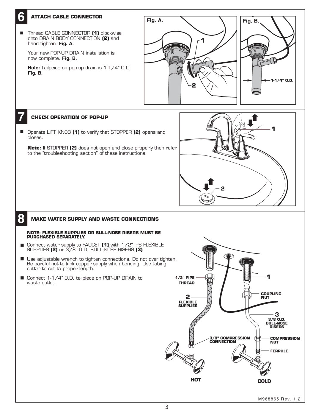
Another characteristic of the 7034 model is its ease of installation and maintenance. Designed to fit into standard bathroom setups, it allows for straightforward installation processes, making it an ideal choice for both new constructions and remodels. Furthermore, its robust materials are selected for longevity, resisting wear and tear from daily use.
The American Standard 7034 also prioritizes comfort. The height and ergonomics of the design are engineered to enhance the user experience, ensuring it is accessible to a wide range of users. This thoughtful consideration makes it a favored option among homeowners and renters alike, looking for efficiency and comfort in their bathroom spaces.
Overall, the American Standard 7034 is a well-rounded bathroom fixture that combines style, efficiency, and reliability, catering to the demands of modern living while contributing to sustainable practices in water usage. With its user-friendly features and advanced technologies, it stands out as a trustworthy choice for any bathroom setting.

