Fig. 1
124mm
155mm
175mm
162mm
108mm
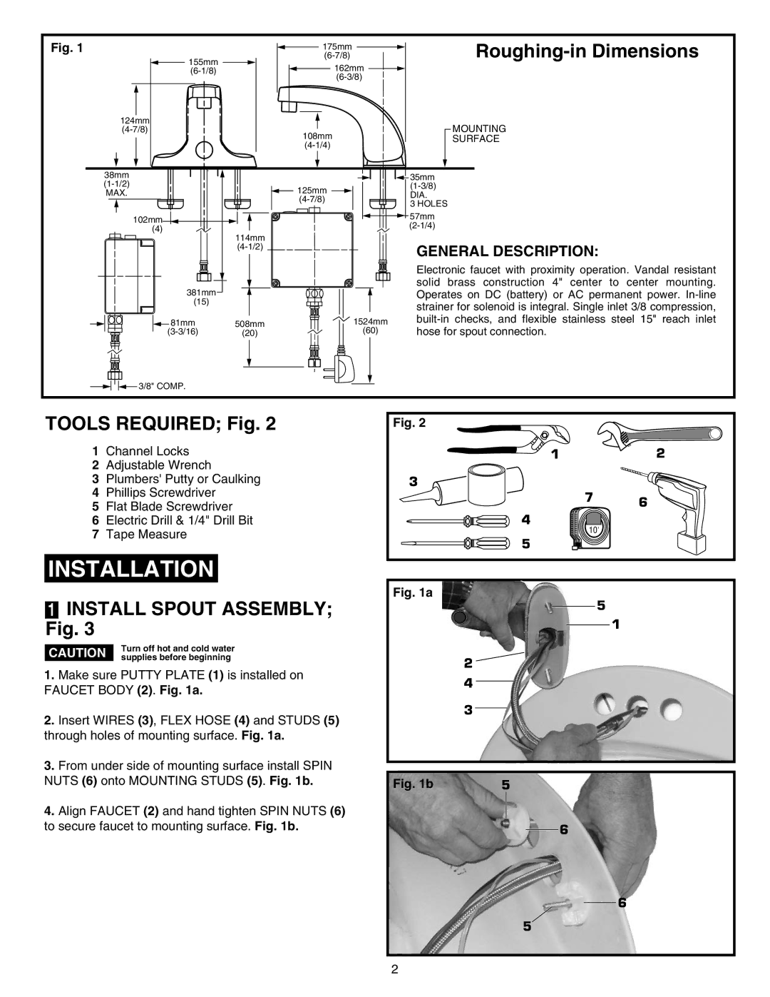
Roughing-in Dimensions
MOUNTING
SURFACE
38mm |
| 35mm |
125mm | ||
MAX. | DIA. | |
| 3 HOLES | |
|
| |
| 102mm | 57mm |
| ||
| (4) | |
| 114mm |
|
| GENERAL DESCRIPTION: | |
|
|
|
|
| Electronic faucet with proximity operation. Vandal resistant | |
381mm |
|
| solid brass construction 4" center to center mounting. | |
|
| Operates on DC (battery) or AC permanent power. | ||
(15) |
|
| strainer for solenoid is integral. Single inlet 3/8 compression, | |
|
|
| ||
81mm | 508mm | 1524mm | ||
hose for spout connection. | ||||
(20) | (60) |
![]() 3/8" COMP.
3/8" COMP.
TOOLS REQUIRED; Fig. 2
1Channel Locks
2Adjustable Wrench
3Plumbers' Putty or Caulking
4 Phillips Screwdriver
5 Flat Blade Screwdriver
6 Electric Drill & 1/4" Drill Bit
7 Tape Measure
INSTALLATION
1INSTALL SPOUT ASSEMBLY; Fig. 3
| Turn off hot and cold water | |
CAUTION | ||
supplies before beginning |
1.Make sure PUTTY PLATE (1) is installed on FAUCET BODY (2). Fig. 1a.
2.Insert WIRES (3), FLEX HOSE (4) and STUDS (5) through holes of mounting surface. Fig. 1a.
3.From under side of mounting surface install SPIN NUTS (6) onto MOUNTING STUDS (5). Fig. 1b.
4.Align FAUCET (2) and hand tighten SPIN NUTS (6) to secure faucet to mounting surface. Fig. 1b.
Fig. 2 |
|
|
1 |
| 2 |
3 | 7 |
|
| 6 | |
|
| |
4 | 10' |
|
|
| |
5 |
|
|
Fig. 1a
5
1
2 ![]()
4
3
Fig. 1b | 5 |
6
6
5
2