Cierre el suministro del agua caliente

1 ¡ATENCIÓN! y fría antes de comenzar.

DESBASTADO

Al soldar, quite el PROTECTOR DE YESO, los CARTUCHOS y los LIMITADORES (SI ESTÁN NOTA PRESENTES). Al terminar de soldar, enjuague el cuerpo de la válvula, vuelva a colocar los

cartuchos y revise los limitadores (si están presentes) y el protector de yeso antes de continuar con la instalación. Utilice sellador para roscas o cinta de Teflon en las conexiones roscadas.

Consulte el diagrama de desbastado antes de continuar.

Conecte el TUBO ELEVADOR (1) a la salida superior "SHR" (ducha) del MÚLTIPLE (2).

Conecte el TUBO DE LLENADO DE LA BAÑERA (3) a la salida inferior "TUB" (bañera).

Las conexiones de suministro son las siguientes:

1/2" (12,7 mm) cobre soldado, para las entradas soldadas

1/2" (12,7 mm) NPT hembra, para las entradas roscadas

Para lograr la posición correcta, la pared terminada debe quedar dentro de la pared lateral del PROTECTOR DE YESO (4).

Si instala la válvula en una pared delgada o de fibra de vidrio, puede utilizar el PROTECTOR DE YESO (4) como soporte.

Corte un agujero de 3" (76 mm) de diámetro en el recinto de la ducha.

Si utilizará LIMITADORES, taladre dos agujeros adicionales de 1" (25 mm) de diámetro para el acceso a los limitadores.

Quite el PROTECTOR DE YESO (4) y gírelo 180 grados para que los agujeros para tornillo indicados correspondan al MÚLTIPLE (2).

Coloque el CAPUCHÓN de la válvula, monte el ESCUDETE y sujételo con tornillos.

Conecte el suministro de agua fría y caliente.

Tapone la tubería de la ducha (5) y la tubería de llenado de la bañera (6). Para tener más apoyo, utilice ABRAZADERAS (7) para tubería sujetas a soportes de madera.

Cierre la válvula, abra el suministro de agua y revise si hay fugas.

Fermer l’alimentation en eau chaude et en

ATTENTION eau froide avant de commencer.

PRÉPARATION

REMARQUE Lorsqu'on soude, enlever la PROTECTION CONTRE LE PLÂTRE, les CARTOUCHES et LES BUTÉES DE RETENUE (S'IL Y EN A). Lorsqu'on a fini de souder, rincer le corps du robinet, remettre les cartouches, les butées

d'arrêt (s'il y en a) et la protection contre le plâtre avant de continuer l'installation. Utiliser un produit d'étanchéité pour filetage ou du ruban Téflon sur les connexions filetées.

Consulter le diagramme de préparation avant de commencer.

Connecter le TUYAU MONTANT (1) à la sortie supérieure du MANIFOLD (2) marquée "SHR".

Connecter le TUYAU DE REMPLISSAGE DE BAIGNOIRE (3) à la sortie inférieure marquée "TUB".

Les connexions pour l'alimentation sont :

Cuivre lisse 12,7 mm (1/2 po.) pour les entrées lisses

NPT femelle 12,7 mm (1/2 po.) pour les entrées filetées

Pour obtenir un bon positionnement, le mur fini doit être à l'intérieur du trou latéral de la PROTECTION CONTRE LE PLÂTRE (4).

Si le robinet est installé sur de la fibre de verrre ou une autre paroi de faible épaisseur, la PROTECTION CONTRE LE PLÂTRE (4) peut être utilisée comme support.

Découper un trou de 76 mm (3 po.) de diamètre dans la cabine de douche.

Si des BUTÉES sont utilisées, percer deux trous supplémentaires de 25 mm (1 po.) pour permettre l'accès aux butées.

Enlever la PROTECTION CONTRE LE PLÂTRE (4), effectuer une rotation de 180 degrés de façon que les trous de vis indiqués correspondent au

MANIFOLD (2).

Pousser le CAPUCHON sur le robinet, placer l'ÉCUSSON par dessus et l'attacher avec les vis.

Connecter les alimentations d'eau chaude et d'eau froide.

Boucher le tuyau de douche (5) et le tuyau de remplissage de baignoire (6). Pour les maintenir, utiliser des ATTACHES (7) de tuyau fixées sur des pièces de bois.

Le robinet étant fermé, ouvrir les alimentations en eau et vérifier qu'il n'y a pas de fuite.

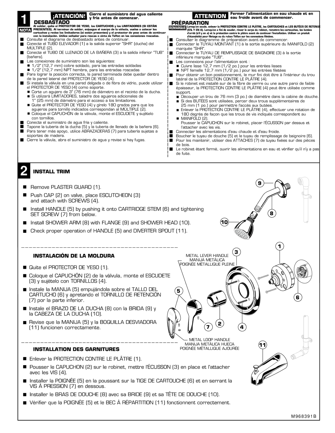
2 INSTALL TRIM

Remove PLASTER GUARD (1).

Push CAP (2) on valve, place ESCUTCHEON (3) and attach with SCREWS (4).

Install HANDLE (5) by pushing it onto CARTRIDGE STEM (6) and tightening

SET SCREW (7) from below.

Install SHOWER ARM (8) with FLANGE (9) and SHOWER HEAD (10).

10

Check proper operation of HANDLE (5) and DIVERTER SPOUT (11).

INSTALACIÓN DE LA MOLDURA


3


METAL LEVER HANDLE


MANIJA METÁLICA


Quite el PROTECTOR DE YESO (1).

POIGNÉE MÉTALLIQUE PLEINE


Coloque el CAPUCHÓN (2) de la válvula, monte el ESCUDETE


(3) y sujételo con TORNILLOS (4).


H


Instale la MANIJA (5) empujándola sobre el TALLO DEL

5


CARTUCHO (6) y apretando el TORNILLO DE RETENCIÓN


(7) por la parte inferior.


Instale el BRAZO DE LA DUCHA (8) con la BRIDA (9) y


la CABEZA DE LA DUCHA (10).


Revise que la MANIJA (5) y la BOQUILLA DESVIADORA

7

2

4

(11) funcionen correctamente.


METAL LOOP HANDLE


MANIJA METÁLICA HUECA


INSTALLATION DES GARNITURES

POIGNÉE MÉTALLIQUE AJOURÉE


Enlever la PROTECTION CONTRE LE PLÂTRE (1).

Pousser le CAPUCHON (2) sur le robinet, mettre l'ÉCUSSON (3) en place et l'attacher avec les VIS (4).

Installer la POIGNÉE (5) en la poussant sur la TIGE DE CARTOUCHE (6) et en serrant la VIS À PRESSION (7) en dessous.

Installer le BRAS DE DOUCHE (8) avec sa BRIDE (9) et sa TÊTE DE DOUCHE (10).

Vérifier que la POIGNÉE (5) et le BEC À RÉPARTITION (11) fonctionnent correctement.

9

8

1

C

11

6

M 9 6 8 3 9 1 B

Page 2
Image 2
American Standard 1495SS.500 Desbastado, Préparation, Install Trim, Instalación DE LA Moldura, Installation DES Garnitures

1495SS.500, 1495.500, T495.500 SERIES specifications

The American Standard 1495.500 and T495.500 Series are renowned for their innovative design and functionality, making them popular choices for modern bathrooms. These models focus on providing exceptional user experiences while adhering to the brand's commitment to quality and durability.

One of the standout features of the American Standard 1495.500 series is its sleek and contemporary aesthetic. Crafted with smooth lines and a minimalist silhouette, these faucets and fixtures complement a variety of bathroom styles, from traditional to ultra-modern. The polished chrome finish not only enhances the visual appeal but also ensures ease of maintenance and long-lasting shine.

In terms of technology, the 1495.500 and T495.500 Series incorporate the exclusive American Standard Speed Connect system. This innovation simplifies installation, allowing for a quicker and more straightforward setup with fewer parts, reducing the risk of leaks and ensuring a reliable connection. This user-friendly design is perfect for both DIY enthusiasts and professional plumbers alike.

Another important characteristic of these models is their water-saving capabilities. The faucets are engineered to provide a balanced flow rate without sacrificing performance, helping to conserve water while still delivering the power needed for effective cleaning and other tasks. These models typically feature a 1.5 GPM (gallons per minute) flow rate, ensuring compliance with WaterSense standards.

The American Standard 1495SS.500, part of the same family, also emphasizes quality with durable materials and construction. It features a ceramic disc valve that provides a smooth operation and ensures no drips or leaks over time. This valve technology significantly extends the lifespan of the faucet, promoting reliability and reducing the need for frequent replacements.

Comfort is another priority, with ergonomic handles that allow for easy temperature and flow adjustments. The design allows for smooth control and helps reduce hand fatigue during use. The faucets are designed for maximum accessibility and ease of use, making them an excellent option for households with varying user needs.

In conclusion, the American Standard 1495.500, T495.500 series, and 1495SS.500 stand out for their design, innovative technology, and water-saving features. These attributes make them ideal choices for anyone looking to enhance their bathroom's functionality while maintaining a stylish appearance. With a focus on durability and user-friendly performance, American Standard continues to be a trusted name in the plumbing industry.