Fig. 1 | Fig. 2 | ||||
|
|
|
|
|
|
|
|
|
|
|
|
|
|
|
|
|
|
|
|
|
|
|
|
|
|
|
|
|
|
|
|
|
|
|
|
|
|
|
|
|
|
|
|
|
|
|
|
|
|
|
|
|
|
|
|
|
|
|
|
Fig. 3 | Fig. 4 | ||||
|
|
|
|
| |
|
|
|
|
|
|
|
|
|
|
|
|
|
|
| |||
|
|
|
|
|
|
|
|
|
|
| |
|
| ||||
|
|
| |||
|
|
|
|
|
|
|
|
|
| ||
|
| ||||
|
|
| |||
|
|
|
|
|
|
Fig. 5 | Fig. 6 | ||||
Troubleshooting
Important Safety Notes
There are a number of (live) tests that are required when fault finding this product. Extreme care should be used at all times to avoid contact with energized components inside the water heater. Only trained and qualified service technicians should attempt to repair this product. Before checking for resistance readings, disconnect the power source to the unit and isolate the item from the circuit (unplug it).
(SV1, SV2, SV3 and POV) Gas valve and Modulating solenoids: (Set meter above 2K)
Wire color | Voltage | Resistance | Connector # | Pin #'s | |
(Main) Pink - Black | 11 ~ 13 VDC | 36.8 ~ 44.8 ohms | H5 | 6 | - 7 |
(SV1) Black - Yellow | 11 ~ 13 VDC | 36.8 ~ 44.8 ohms | H6 | 5 | - 6 |
(SV2) Black - Blue | 11 ~ 13 VDC | 36.8 ~ 44.8 ohms | H7 | 4 | - 6 |
(SV3) Black - Brown | 11 ~ 13 VDC | 36.8 ~ 44.8 ohms | H8 | 3 | - 6 |
(POV) Pink - Pink | 2 ~ 15 VDC | 67 ~ 81 ohms | H3 | 9 | - 10 |
(M) Water Flow Control Device Servo or Geared Motor:
Red - Blue | 11 ~ 13 VDC | 22 ~ 28 ohms | F7 | 9 | - 10 |
Grey - Brown | 4 ~ 6 VDC | N / A | F7 | 5 | - 7 |
Grey - Yellow | N / A | N / A | F7 | 5 | - 8 |
NOTE: The grey wire listed above turns to black at F connector on the PCB. (QS) Water Flow Sensor:
Black - Red | 11 ~ 13 VDC | 5.5 ~ 6.2 K ohms | F2 | 1 - 3 |
Yellow - Black | 4 ~ 7 VDC | 1 ~ 1.4 Mega ohms | F2 | 2 - 3 |
By-pass Flow Control (By-pass servo model ONLY):
Brown - White | 2 | ~ 6 VDC |
| G1 | 1 - 5 |
Orange - White | 15 ~ 35 ohms | G1 | 2 - 5 | ||
Yellow - White | (Unit in operating mode) | G1 | 3 - 5 | ||
|
|
| G1 | 4 - 5 | |
(IG) Ignition System: |
|
|
|
|
|
|
|
|
|
| |
Grey - Grey | 90 ~ 110 VAC | N / A | C1 | 1 - 2 | |
(FM) Combustion Fan Motor: |
|
|
| ||
|
|
|
|
|
|
Red - Black | 6 | ~ 45 VDC | N / A | E1 | 1 - 2 |
White - Black | 5 | ~ 10 VDC | 9.2 ~ 9.4 K ohms | E1 | 2 - 4 |
Yellow - Black | 11 ~ 13 VDC | 3.5 ~ 3.9 K ohms | E1 | 2 - 3 | |
Set your meter to the hertz scale. Reading across the white and black wires at terminals 2 and 4 you should read between 60 and 420 hertz.
Thermal Fuse / Overheat Switch:
Red - Red | 11 ~ 13 VDC | Below 1 ohms | F6 | F6 - H12 | |
H1 | |||||
|
|
|
|
Flame Rod:
Place one lead of your meter to the flame rod and the other to ground. With the unit running you should read between
Heat Exchanger and Outgoing Water Temperature Thermistors:
Check all thermistors by inserting meter leads into each end of the thermistor plug. Set your meter to the 20 K scale and read resistance. Applying heat to the thermistor bulb should decrease the resistance. Applying ice to the thermistor bulb should increase the resistance. See below for examples of typical temperatures and resistance readings.
Example: | 59°F = 11.4 ~ 14K | 140°F = 2.2 ~ 2.7K |
|
| ||||
|
| 86°F = 6.4 ~ 7.8K | 221°F = 0.6 ~ 0.8K |
|
| |||
|
| 113°F = 3.6 ~ 4.5K |
|
|
|
| ||
Outgoing Water Thermistor: |
|
|
|
|
|
|
| |
|
|
|
|
|
|
|
| |
White - White | N / A |
|
| See example above | F5 | 3 | - 4 | |
Heat Exchanger Temperature Thermistor: |
|
|
|
|
| |||
|
|
|
|
|
|
|
| |
Pink - White | N / A |
|
| See example above | F4 | 3 | - 11 | |
Intake Air Thermistor (Indoor model ONLY) |
|
|
|
|
| |||
|
|
|
|
|
|
|
| |
Orange - White | N / A |
|
| See example above | F3 | 3 | - 12 | |
Surge Protector: |
|
|
|
|
|
|
|
|
|
|
|
|
|
|
| ||
Black - White | 108 ~ 132 VAC |
| N / A |
| D2 | 1 | - 3 | |
Blue - Brown | 108 ~ 132 VAC |
| N / A |
| D1 | 1 | - 3 | |
With the power off you can check the continuity through the surge protector. Place a meter lead on the top pin #1 of the surge protector and pin #3 on the bottom of the surge protector. Check across the top pin #3 and bottom pin #1. If you read continuity across these two points then the surge protector is good. If you do not get continuity then replace the surge protector.
Remote Controls:
Terminals B1 | 10 ~ 13 VDC | 1.5 ~ 3.0 K ohms | B | 1 - 3 |
Frost Protection:
This unit has frost protection heaters mounted at different points to protect the water heater from freezing. The heaters located on the hot water outlet line should have a resistance reading of
Amp Fuses:
This unit has one inline (3) amp glass fuses. Remove the fuse and check continuity through it. If you have continuity through the fuse then it is good. Otherwise the fuse is blown and must be replaced.
|
|
|
|
|
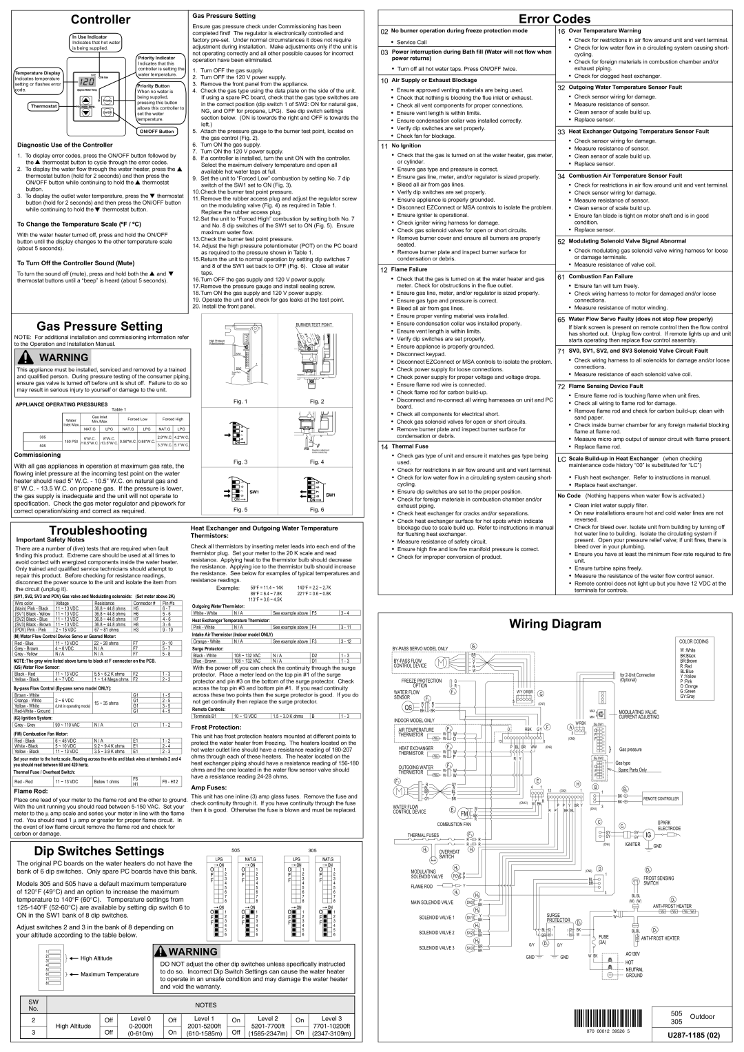
| Wiring Diagram |
|
|
|
| |||||||||
|
|
|
|
|
| G1 |
|
|
|
|
|
|
|
|
|
|
|
| COLOR CODING |
|
|
|
|
|
|
|
|
|
|
|
|
|
| W :White | |||||
|
|
|
|
|
|
|
|
|
|
|
|
|
|
| |||||
|
|
|
|
|
| BR |
|
|
|
|
|
|
|
|
|
|
|
| |
|
|
|
|
|
|
|
|
|
|
|
|
|
|
|
|
|
| BK:Black | |
|
|
|
| O |
|
|
|
|
|
|
|
|
|
|
|
| BR:Brown | ||
|
|
|
| Y |
|
|
|
|
|
|
|
|
|
|
|
| |||
CONTROL DEVICE |
|
|
|
| R |
|
|
|
|
|
|
|
|
|
|
|
| R :Red | |
|
|
|
|
|
| W |
|
|
|
|
|
|
|
|
|
| for | BL:Blue | |
|
|
|
|
|
|
|
|
|
|
|
|
|
|
|
|
| Y :Yellow | ||
FREEZE PROTECTION |
| G |
|
|
|
|
|
|
|
|
|
|
|
| (Optional) |
| P :Pink | ||
OPTION |
|
| R |
|
|
|
|
|
|
|
|
|
|
|
|
|
| O :Orange | |
WATER FLOW |
|
|
| F1 |
|
| W Y O RBR |
| G |
|
|
|
|
|
|
| G :Green | ||
SENSOR | F2 |
|
|
|
|
|
|
|
|
|
|
|
|
|
|
| GY:Gray | ||
|
|
|
|
| 5 | 1 |
|
|
|
|
|
|
|
|
|
| |||
|
|
|
|
|
|
|
|
|
|
|
|
|
|
|
|
| |||
QS | R | R |
|
|
|
|
| (CN7) |
|
|
|
|
|
|
|
| |||
|
|
|
|
|
|
|
|
|
|
|
|
|
|
| |||||
Y | Y |
|
|
|
|
|
|
|
|
|
|
|
|
|
| MODULATING VALVE |
| ||
| BK | BK |
|
|
|
|
|
|
|
|
|
|
|
| MAX |
|
| ||
INDOOR MODEL ONLY |
|
|
|
|
|
|
|
|
|
|
|
| MIN |
| CURRENT ADJUSTING |
| |||
|
|
|
|
|
|
|
|
|
|
| W RBK | Dip SW1 |
|
|
| ||||
|
|
| F3 |
|
|
|
|
|
|
|
| F | A |
|
|
| |||
AIR TEMPERATURE |
|
| O | RBK |
| G Y |
| O | 1 |
|
|
| |||||||
W |
|
|
| 3 | 1 | 2 |
|
|
| ||||||||||
THERMISTOR |
| W |
|
|
|
|
|
|
|
| F | 3 |
|
|
| ||||
|
|
| W | O |
| 13 |
|
|
|
| 1 |
| (CN9) | F | 4 |
|
|
| |
|
|
|
|
|
|
|
|
| 5 |
|
|
| |||||||
HEAT EXCHANGER | F4 |
|
| P | BL BR | WW |
|
| (CN5) |
|
|
| 6 |
|
|
| |||
W |
|
|
|
|
|
| 7 | Gas pressure |
|
| |||||||||
W |
|
|
|
|
|
|
|
|
|
|
| 8 |
|
| |||||
THERMISTOR |
|
|
|
|
|
|
|
|
|
|
|
|
|
|
|
| |||
|
|
| W | P |
|
| R Y |
|
|
|
|
|
|
| Dip SW2 | Gas type |
|
| |
|
|
| F5 |
|
|
|
|
|
|
|
|
|
|
|
| 1 |
|
| |
OUTGOING WATER |
|
|
|
|
|
|
|
|
|
|
| O | 2 | Spare Parts Only |
| ||||
W | W |
|
|
|
|
|
|
|
|
|
| 3 |
| ||||||
THERMISTOR |
|
|
|
|
|
|
|
|
|
|
| F | 4 |
| |||||
|
|
|
|
|
|
|
|
|
|
|
| 5 |
|
|
| ||||
F7 |
|
| W | W |
|
|
|
| E |
|
|
|
| F | 6 |
|
|
| |
R |
|
| GY |
|
|
|
|
|
|
| H | B |
|
|
|
| |||
|
|
|
|
|
| 4 |
| 1 |
|
|
|
|
|
| |||||
| BL |
|
| R |
|
|
|
| 12 | (CN2) | 1 |
| B1 |
|
| ||||
| BR |
|
| BL |
|
|
|
|
|
|
|
| 1 |
|
| ||||
| Y |
|
| Y |
|
|
|
|
|
|
|
|
|
|
|
| BK | REMOTE CONTROLLER |
|
| GY |
|
| BR |
|
| (CN12) |
| Y |
| R |
|
|
|
|
| BK |
| |
WATER FLOW |
|
|
|
|
|
| W | BK | P | P Y | BR Y |
| 3 |
|
| ||||
|
|
|
|
| W |
|
|
|
|
|
|
| |||||||
|
|
| E1 |
|
|
|
|
|
| (CN1) |
|
|
| ||||||
|
|
|
|
|
|
|
|
| R P | BK BL |
|
|
|
| |||||
CONTROL DEVICE |
|
| FM | Y |
|
|
|
|
|
|
|
|
|
|
| ||||
|
|
|
|
| BK |
|
|
|
|
|
|
|
|
|
|
|
|
| |
|
| COMBUSTION FAN | R |
|
|
|
|
|
|
|
| C |
|
| SPARK |
| |||
|
|
|
|
|
|
|
|
|
|
|
| C1 |
| ||||||
|
|
|
|
|
|
|
|
|
|
|
|
| ELECTRODE | ||||||
|
|
|
|
|
|
|
|
|
|
|
|
|
|
|
|
| |||
|
|
|
|
|
|
|
|
|
|
|
|
|
|
|
| GY | GY | ||
THERMAL FUSES |
|
| F6 |
|
|
|
|
|
|
|
|
| IG |
| |||||
|
|
|
|
|
|
|
|
|
|
| GY | GY |
| ||||||
|
|
|
|
| R | R |
|
|
|
|
|
|
|
|
|
| IGNITER |
|
|
|
|
|
|
| R | R |
|
|
|
|
|
|
|
|
| (CN4) |
|
| |
505 | 305 |
The original PC boards on the water heaters do not have the bank of 6 dip switches. Only spare PC boards have this bank.
Models 305 and 505 have a default maximum temperature of 120°F (49°C) and an option to increase the maximum temperature to 140°F (60°C). Temperature settings from
Adjust switches 2 and 3 in the bank of 8 depending on your altitude according to the table below.
![]() WARNING
WARNING
DO NOT adjust the other dip switches unless specifically instructed to do so. Incorrect Dip Switch Settings can cause the water heater to operate in an unsafe condition and may damage the water heater and void the warranty.
H2 | OVERHEAT | H1 |
|
|
|
|
|
|
|
| GND | |
|
|
|
|
|
|
|
|
| ||||
|
|
|
|
|
|
|
|
|
|
| ||
| SWITCH |
|
|
|
|
|
|
|
|
|
| |
MODULATING |
| H3 | P |
|
|
|
|
|
| (CN3) D |
| D3 |
|
|
|
|
|
|
|
| 1 |
|
| ||
SOLENOID VALVE | POV |
|
|
|
|
|
|
| FROST SENSING | |||
|
|
| P |
|
|
|
|
|
| BL |
| |
FLAME ROD |
|
| Y |
|
|
|
|
|
| BR |
| SWITCH |
| H4 |
|
|
|
|
|
|
|
|
| ||
|
|
| H5 |
|
|
|
|
| 3 | BL BL |
| |
|
|
|
|
|
|
|
|
|
| D5 | ||
MAIN SOLENOID VALVE | SV0 | P |
|
|
|
|
|
| (W) (W) | |||
BK |
|
|
|
|
|
|
| |||||
|
|
|
|
|
|
|
|
|
|
| ||
|
|
|
| H6 |
|
| SURGE |
|
| W |
| |
SOLENOID VALVE 1 | SV1 | Y |
|
|
|
| W |
| ||||
BK |
|
| PROTECTOR | D2 |
|
| ||||||
|
|
|
|
|
|
|
|
| ||||
|
|
|
| H7 |
|
|
|
|
|
|
| |
|
|
|
|
| BL | 1 |
| BK |
| BLBL | D4 | |
SOLENOID VALVE 2 | SV2 | BL |
| 3 |
| |||||||
|
|
| ||||||||||
BK |
| BR 3 | 1 | W | FUSE | |||||||
|
|
|
|
| ||||||||
|
|
|
| H8 |
|
|
|
|
| |||
|
|
|
| G/Y | D1 | G/Y |
| (3A) |
|
| ||
SOLENOID VALVE 3 | SV3 | BR |
|
|
| |||||||
|
|
|
|
|
|
|
| |||||
|
|
|
| BK |
|
|
|
|
|
| AC120V |
|
|
|
|
|
| GND |
|
| GND |
| W BK |
| |
|
|
|
|
|
|
|
|
|
| |||
HOT
NEUTRAL
![]() GROUND
GROUND
SW |
|
|
|
| NOTES |
|
|
|
| |
No. |
|
|
|
|
|
|
|
| ||
|
|
|
|
|
|
|
|
| ||
2 |
| Off | Level 0 | Off | Level 1 | On | Level 2 | On | Level 3 | |
| High Altitude |
|
|
|
| |||||
3 | Off | On | Off | On | ||||||
| ||||||||||
|
|
|
|
|
|
|
|
|
|
070 00012 39526 5
505 Outdoor
305