PLEASE READ THE FOLLOWING INSTRUCTIONS CAREFULLY

IMPORTANT GENERAL SAFETY INFORMATION -

ADDITIONAL SPECIFIC SAFETY ALERTS APPEAR IN THE FOLLOWING INSTRUCTIONS.

EXPLOSION HAZARD. Failure to follow instruc- tions in the accompanying product manual can cause rupture or explosion, possibly causing serious or fatal injury, leak-

ing or flooding and/or property damage.

Location of the FIRE-X-TROL®

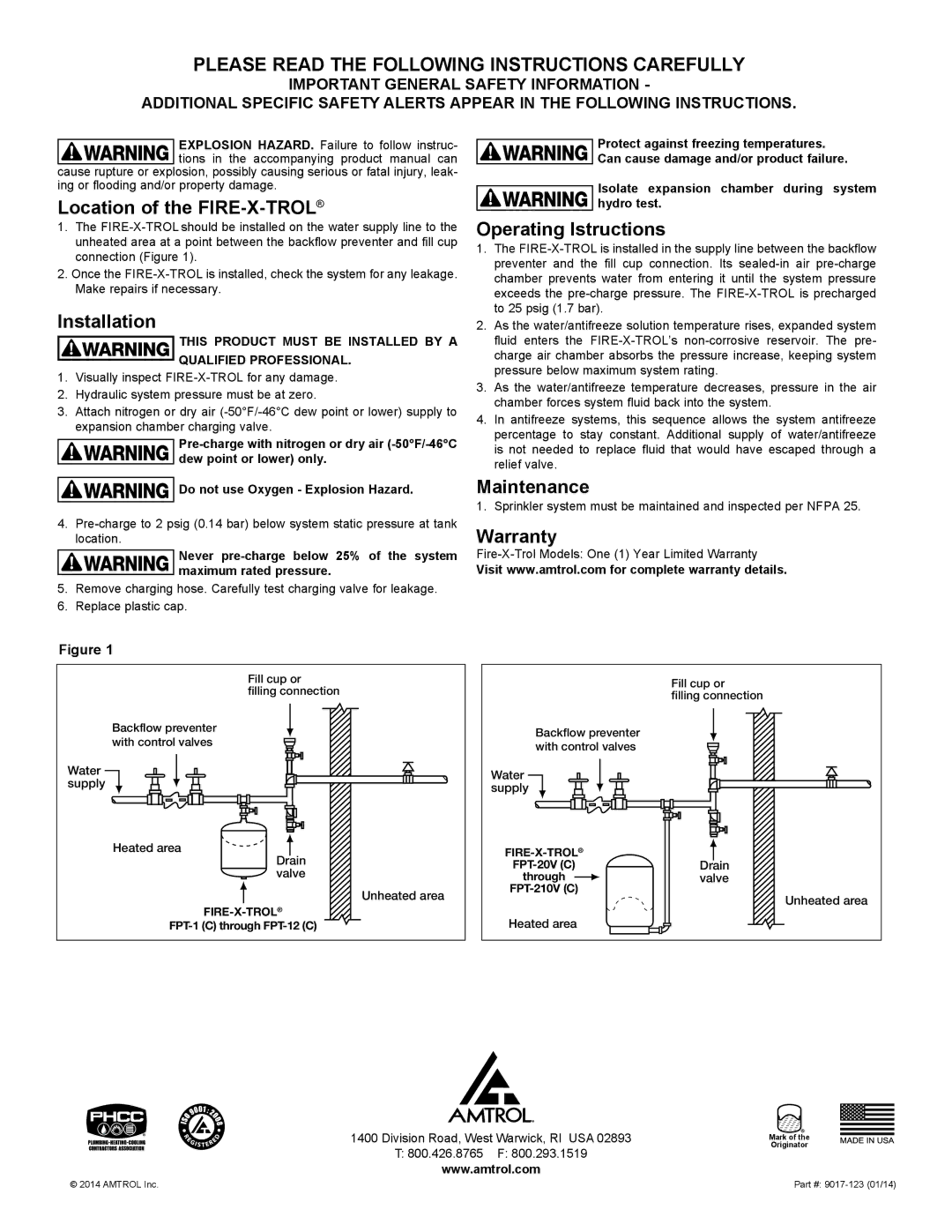
1.The FIRE-X-TROL should be installed on the water supply line to the unhea­ted area at a point between the backflow preventer and fill cup connection (Figure 1).

2.Once the FIRE-X-TROL is installed, check the system for any leakage. Make repairs if necessary.

Installation

THIS PRODUCT MUST BE INSTALLED BY A

QUALIFIED PROFESSIONAL.

1.Visually inspect FIRE-X-TROL for any damage.

2.Hydraulic system pressure must be at zero.

3.Attach nitrogen or dry air (-50°F/-46°C dew point or lower) supply to expansion chamber charging valve.

Pre-charge with nitrogen or dry air (-50°F/-46°C dew point or lower) only.

Do not use Oxygen - Explosion Hazard.

4.Pre-charge to 2 psig (0.14 bar) below system static pressure at tank location.

Never pre-charge below 25% of the system maximum rated pressure.

5.Remove charging hose. Carefully test charging valve for leakage.

6.Replace plastic cap.

Protect against freezing temperatures.

Can cause damage and/or product failure.

Isolate expansion chamber during system hydro test.

Operating Istructions

1.The FIRE-X-TROL is installed in the supply line between the backflow preventer and the fill cup connection. Its sealed-in air pre-charge chamber prevents water from entering it until the system pressure exceeds the pre-charge pressure. The FIRE-X-TROL is precharged to 25 psig (1.7 bar).

2.As the water/antifreeze solution temperature rises, expanded system fluid enters the FIRE-X-TROL’s non-corrosive reservoir. The pre- charge air chamber absorbs the pressure increase, keeping system pressure below maximum system rating.

3.As the water/antifreeze temperature decreases, pressure in the air chamber forces system fluid back into the system.

4.In antifreeze systems, this sequence allows the system antifreeze percentage to stay constant. Additional supply of water/antifreeze is not needed to replace fluid that would have escaped through a relief valve.

Maintenance

1. Sprinkler system must be maintained and inspected per NFPA 25.

Warranty

Fire-X-Trol Models: One (1) Year Limited Warranty

Visit www.amtrol.com for complete warranty details.

Figure 1


Fill cup or


filling connection

Backflow preventer

Backflow preventer

with control valves

with control valves


Water

Water

supply

supply


Heated area


FIRE-X-TROL®


Drain


FPT-20V (C)


valve


through


Unheated area

FPT-210V (C)


FIRE-X-TROL®


Heated area

FPT-1 (C) through FPT-12 (C)


Fill cup or

filling connection

Drain valve

Unheated area

1400 Division Road, West Warwick, RI USA 02893

T:800.426.8765 F: 800.293.1519 www.amtrol.com

Mark of the Originator

© 2014 AMTROL Inc.

Part #: 9017-123 (01/14)

Page 2
Image 2
Amtrol fpt-1 warranty Location of the FIRE-X-TROL, Installation, Operating Istructions, Maintenance, Warranty

fpt-1 specifications

The Amtrol FPT-1 is a pivotal solution in the realm of water treatment and storage, designed specifically for residential and commercial applications. This innovative product is engineered to meet various water management needs, showcasing a blend of advanced features, cutting-edge technologies, and user-friendly characteristics.

One of the standout features of the Amtrol FPT-1 is its exceptional durability. Constructed with robust materials, the unit is designed to withstand rigorous conditions, ensuring a long service life. The product is also equipped with a high-quality internal diaphragm, which maintains pressure and minimizes the risk of water hammering, making it a reliable choice for maintaining consistent water pressure in plumbing systems.

The Amtrol FPT-1 employs state-of-the-art bladder technology, which separates air and water. This design allows for the efficient storage of water while preventing contamination and ensuring the integrity of the water supply. With a maximum operating pressure that often exceeds industry standards, the FPT-1 guarantees reliable performance even under heavy use.

Another significant characteristic of the FPT-1 is its easy installation process. The unit is designed with user convenience in mind, featuring a compact size that allows for versatile placement in both homes and businesses. Users can quickly connect the FPT-1 to existing plumbing systems without the need for extensive modifications, making it a practical choice for quick upgrades.

Moreover, the Amtrol FPT-1 is engineered for energy efficiency. By optimizing the use of stored water, it reduces the need for constant pump activation, which can lead to energy savings over time. This not only benefits users financially but also contributes to a more sustainable approach to water management.

In summary, the Amtrol FPT-1 effectively combines durability, innovative bladder technology, ease of installation, and energy efficiency. A perfect addition to any water system, it serves as a testament to Amtrol's commitment to quality and customer satisfaction. Whether for residential, commercial, or industrial use, the FPT-1 stands out as a reliable solution for effective water storage and pressure management. Its reputation for excellence makes it a preferred choice among industry professionals and homeowners alike.