Installation Guide
Overview
The
Specifications
CB-MVPWDS (FG037-10) Specifications
Dimensions (HWD): | • 8 3/16" x 12" x 3 1/4" |
| • 20.7 mm x 30.4 mm x 8.2 mm |
|
|
Included Accessories | • Five mountings screws |
| TYPE B, |
| |
|
|
Certifications: | • cTUVus Listed |
|
|
WARNING: INSTALLER, LEAVE A GAP BETWEEN THE STUD AND
This gap allows the installation of the drywall/sheetrock after the
Note: The most important thing to remember when mounting this
Installing the CB-MVPWDS Rough-In Box
The
Note: Installation procedures and configurations vary depending on the installation environment.
When mounting the
Refer to SP596502 for detailed installation dimensions (see reverse).
•It is recommended that you cut out the surface slightly smaller than what is outlined in the installation drawings so that you can make any necessary cutout adjustments.
•The
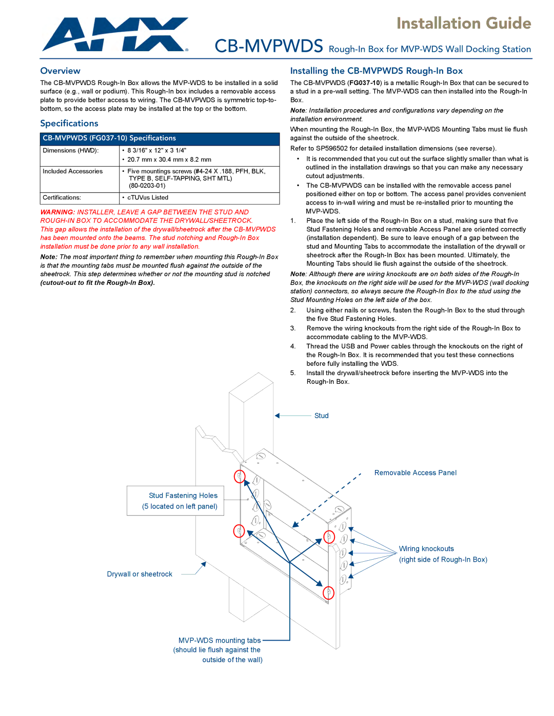
1.Place the left side of the
Note: Although there are wiring knockouts are on both sides of the
2.Using either nails or screws, fasten the
3.Remove the wiring knockouts from the right side of the
4.Thread the USB and Power cables through the knockouts on the right of the
5.Install the drywall/sheetrock before inserting the
Stud
Removable Access Panel
Stud Fastening Holes (5 located on left panel)
Wiring knockouts
![]() (right side of
(right side of
Drywall or sheetrock