Installation Guide
MET-13 Metreau™ 13-Button Keypad
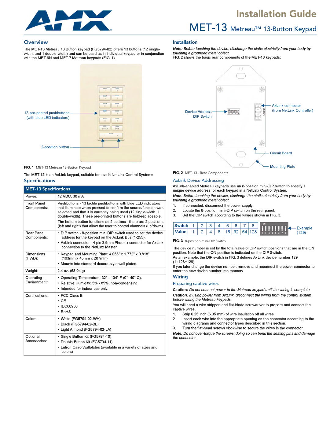
Overview
The
Installation
Note: Before touching the device, discharge the static electricity from your body by touching a grounded metal object.
FIG. 2 shows the basic rear components of the MET-13 keypads:
|
|
|
|
|
| AxLink connector |
|
|
|
|
|
| |
13 |
| Device Address |
|
|
| (from NetLinx Controller) |
|
|
|
|
| ||
(with blue LED indicators) |
| DIP Switch |
|
| ||
|
|
|
|
|
| Circuit Board |
|
|
|
|
|
| |
FIG. 1 | FIG. 2 |
|
|
|
| Mounting Plate |
|
|
| ||||
The | ||||||
|
|
|
|
|
| |
Specifications
MET-13 Specifications
Power: | 12 VDC, 30 mA |
|
|
Front Panel | Pushbuttons - 13 tactile pushbuttons with blue LED indicators |
Components: | that illuminate when pressed to confirm the source/function was |
| selected and that it is currently being used (12 |
| |
| The bottom button functions as 2 buttons - there are 2 positions |
| (left and right) that allow the user to control channels (up/down). |
|
|
Rear Panel | • DIP switch - |
Components: | address for the keypad on the AxLink Bus |
| • AxLink connector - |
| connection to the NetLinx Master. |
|
|
Dimensions | • Keypad and Mounting Plate: 4.055" x 1.772" x 0.818" |
(HWD): | (103mm x 45mm x 207mm) |
| • Mounts into standard |
|
|
Weight: | 2.4 oz. (68.04 g) |
|
|
Operating | • Operating Temperature: 32° - 104° F (0°- 40° C). |
Environment: | • Relative Humidity: 5% - 85%, |
| • Intended for indoor use only. |
|
|
Certifications: | • FCC Class B |
| • CE |
| • IEC60950 |
| • RoHS |
|
|
Colors: | • White |
| • Black |
| • Light Almond |
|
|
Optional | • Single Button Kit |
Accessories: | • Double Button Kit |
| • Lutron Cairo Wallplates (available in a variety of sizes and |
| colors) |
|
|
AxLink Device Addressing
Note: Before touching the device, discharge the static electricity from your body by touching a grounded metal object.
1.If connected, disconnect the power supply.
2.Locate the
3.Set the DIP switch according to the values shown in FIG. 3.
Switch | 1 | 2 | 3 | 4 | 5 | 6 | 7 | 8 |
|
| Example |
Value | 1 | 2 | 4 | 8 | 16 | 32 | 64 | 128 | (129) | ||
FIG. 3 8-position mini-DIP Switch
The device number is set by the total value of DIP switch positions that are in the ON position. Note that the ON position is indicated on the DIP Switch.
As an example, the DIP switch in FIG. 3 defines AxLink device number 129 (1+128=129).
If you later change the device number, remove and reconnect the power connector to enter the new device number into memory.
Wiring
Preparing captive wires
Caution: Do not connect power to the Metreau keypad until the wiring is complete.
Caution: If using power from AxLink, disconnect the wiring from the control system before wiring the Metreau keypads.
You will need a wire stripper, and
1.Strip 0.25 inch (6.35 mm) of wire insulation off all wires.
2.Insert each wire into the appropriate opening on the connector according to the wiring diagrams and connector types described in this section.
3.Turn the
Note: Do not