Wiring
Preparing captive wires
Caution: Do not connect power to the Metreau keypad until the wiring is complete.
Caution: If using power from AxLink, disconnect the wiring from the control system before wiring the Metreau keypads.
You will need a wire stripper, and flat-blade screwdriver to prepare and connect the captive wires.
1.Strip 0.25 inch (6.35 mm) of wire insulation off all wires.
2.Insert each wire into the appropriate opening on the connector according to the wiring diagrams and connector types described in this section.
3.Turn the flat-head screws clockwise to secure the wires in the connector.
Note: Do not over-torque the screws; doing so can bend the seating pins and damage the connector.
Wiring guidelines
Metreau keypads require 12 VDC power to operate properly. The necessary power is supplied via the AxLink or SWT cable. The maximum wiring distance is determined by power consumption, supplied voltage, and the wire gauge used for the cable. The following table lists wire sizes and the maximum lengths allowable based on the maximum power consumption rating of 170 mA.
AxLink Wiring Guidelines at 170 mA
Wire Size | Maximum Wiring Length |
18 AWG | 690.42 feet (210.43 m) |
20 AWG | 436.80 feet (133.13 m) |
22 AWG | 272.33 feet (83.00 m) |
24 AWG | 171.66 feet (52.32 m) |
The maximum wiring lengths for using AxLink power are based on a minimum of
13.5volts available. If the distance is greater than what is listed in the table, consult the Metreau Keypads Operation/Reference Guide for wiring with external power sources.
AxLink Data and Power Connections
Connect the control system's AxLink connector to the AxLink connector on the rear panel of the Metreau Keypad for data and 12 VDC power as shown in FIG. 5.
PWR + | | | | | | | | | | | PWR + |
| | | | | | | | | |
AXP | | | | | | | | | | | AXP |
| | | | | | | | | |
AXM | | | | | | | | | | | AXM |
| | | | | | | | | |
GND - | | | | | | | | | | | GND - |
| | | | | | | | | | | |
Metreau Keypad | Control System |
FIG. 5 AxLink straight-thru wiring
Using AxLink for Data with an Auxiliary Power Supply
Use an auxiliary 12 VDC power supply when the distance between the controller and server exceeds the limits described in the Wiring guidelines section. Connect only the GND (-) wire on the AxLink connector when using an auxiliary 12 VDC power supply.
Connect the NetLinx Controller’s AxLink connector to the AxLink connector on the rear panel of the Metreau keypad, as shown in FIG. 6.
12 VDC power supply PWR (+)  GND (-)
PWR + | | | | | | | | | PWR + |
| | | | | | | | |
AXP | | | | | | | | | | AXP |
| | | | | | | |
AXM | | | | | | | | | | AXM |
GND - | | | | | | | | | | GND - |
| | | | | | |
NetLinx Controller | Metreau keypad |
FIG. 6 AxLink and 12 VDC power supply wiring diagram
Note: If you are not using power from AxLink, disconnect the wiring from the controller before wiring the Metreau keypad. Make sure the auxiliary power supply’s PWR (+) is not connected to the controller’s AxLink connector.
AxLink Status LED
The AxLink Status LED (located next to the AxLink connector), lights to indicate AxLink power/data status (see Operation / Reference Guide for details).
If the LED is on and not flashing, disconnect the AxLink connector and recheck all AxLink connections. Then, reconnect the AxLink connector to the panel and verify the LED is flashing once per second.
Mounting Procedures
AMX recommends mounting Metreau keypads in standard U.S.-style decora wallboxes:
•Conduit box should meet NEC specs (section 370)
•Minimum internal clearance of (HWD) 2-5/8" x 1-3/4" x 1-5/8".
Note: Before touching the device, discharge the static electricity from your body by touching a grounded metal object.
Wallbox Mounting
1.Use the cutout dimension for the wallbox to cutout the install surface.
2.Connect the AxLink connector (or SWT cable connectors) to the rear of the keypad.
3.Place the Mounting Plate on the wallbox; align the screw holes with the mount- ing holes and fasten the Mounting Plate to the wallbox using the screws sup- plied.
Note: Do not overtighten the screws when mounting the Mounting Frame. The device should be flush with mounting surface.
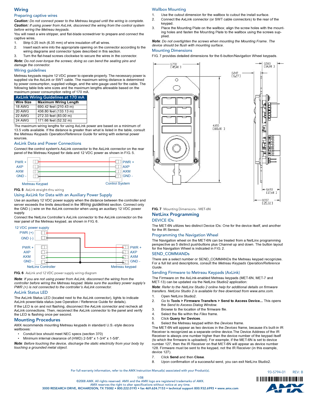
Mounting Dimensions
FIG. 7 provides detailed dimensions for the 6-button/Navigation Wheel keypads.
FIG. 7 Mounting Dimensions - MET-6N
NetLinx Programming
DEVICE IDs
The MET-6N utilizes two distinct Device IDs: One for the device itself, and another for the IR Sensor.
Programming the Navigation Wheel
The Navigation wheel on the MET-6N can be treated from a NetLinx programming perspective as 5 distinct pushbuttons plus Channel up and down. The button layout for the Navigation Wheel is indicated in FIG. 2.
SEND_COMMANDs
There are a select number or SEND_COMMANDs the Metreau keypad recognizes. For a full list and descriptions, consult the Metreau Keypads Operation/Reference Guide.
Sending Firmware to Metreau Keypads (AxLink)
The Firmware on the AxLink-enabled Metreau keypads (MET-6N, MET-7 and MET-13) can be updated via the NetLinx Studio2 application:
Note: Refer to the NetLinx Studio 2 online help for additional details on firmware transfers. NetLinx Studio 2 is available for free download from www.amx.com.
1.Open NetLinx Studio2.
2.Go to Tools > Firmware Transfers > Send to Axcess Device... This opens the Send to Axcess Dialog Window.
3.Browse to the location of the firmware file.
4.Select the file within the Files frame.
5.Click Query for Devices.
6.Select the Metreau keypad within the Devices frame.
The MET-6N will appear as two devices in the Devices frame, because it’s built-in IR Receiver is recognized as a separate online device.The Device Address of the IR Receiver is always one number higher than the device number of the keypad itself (to which the firmware is uploaded). For example, if the MET-6N is set to device number 127, then the IR Receiver on that MET-6N will appear as device number
128.Firmware must be sent to the keypad, not the IR Receiver (in this example, device 127).
7.Click Send and then Close.
8.Upon confirmation of a successful send, you can exit NetLinx Studio2.