Connecting UDM RX01/RX02 Receivers to the UDM-0404
1.Connect a standard Cat5/6 cable to the port marked UDM on the UDM Hub.
2.Connect the other end of the Cat5/6 cable to the “UDM Hub” port on the UDM-RX01 or RX02 Receiver.
3.When the power is switched on 2 LEDs will be visible at the Hub port – Amber (phantom power enabled) and Green (UDM receiver connected to Hub port).
Configuration Overview
Each UDM Hub can be configured for the correct network environment. It is also possible to configure each Hub for the correct date and time. Configuration options are available via the UDM Hub’s built-in Browser Interface.
Refer to the UDM-0404 Endeleo Multi-Format Distribution Hub Operation/Reference Guide for information on input configuration, user control, passthrough mode, video compensation, date/time configuration, creating scheduled events and scheduled presets.
Connecting to the UDM-0404
1.With the TCP/IP address configured, connect the UDM-0404 to your network equipment (switch, hub, or serial port) - or if required use an Ethernet Cross- over cable to connect your PC directly.
2.Enter the IP address into the address field within a browser window. The default IP address of the UDM-0404 is 192.168.0.96.
3.To connect to the UDM-0404, a password is required (FIG. 2).
FIG. 2 Endeleo Login screen
•The username should be left blank. •The password is admin.
•The password is case sensitive.
4.On initial connection, the Status page is displayed.
Network Configuration
Hubs can be configured for the network environment using the Setup page.
Note: The UDM-0404 does not support DHCP. Always configure a static IP Address.
1.Specify the following network options for the Hub:
a.Hub IP Address, Subnet Mask and Default Gateway;
b.UDP Port (default = 2008)
c.Hub name (maximum of 30 characters).
2.Click on Update to save the new settings to the Hub (FIG. 3).
FIG. 3 Network Settings
Note: All changes are immediate - once the IP address of the hub has been changed redirect the web browser to the changed address.
Restoring Hub Configuration and Connections on Power Up
To ensure the configuration settings for the Hub are retained each time the hub boots, ensure the Restore configuration on power up and Restore connections on power up options (at the bottom of the Setup page) have been enabled (FIG. 4).
FIG. 4 Restoring configuration on power up
Note: Failure to select the Restore Configuration and Connection options will mean the Hub configuration and connections will need to be re-configured if the Hub is reset.
Hub Reset
To reset the Hub, Click the Reset Hub button (FIG. 4).
Note: A power down of the Hub is required to complete the reset procedure.
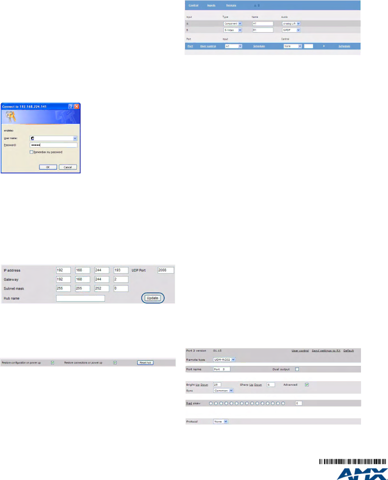
Input Configuration
The options on the Inputs page allow you to specify the video types and audio sources being presented to each input port and where appropriate renaming these.
1.Select the Inputs link at the top of the Status page to invoke the Input Configu- ration page (FIG. 5).
FIG. 5 Input Configuration page
2.Use the Type drop-down menus to select the appropriate Input Type for each input).
•For VGA, Component, S-Video, and Composite inputs, only one connection is possible per input port.
•If the Input Type is Composite, then the screen will refresh and enable the administrator to name each of the 3 available composite sources separately.
3.Name the input Type(s) appropriately.
Configuring Audio Types For Inputs
Audio types (Analog L/R or S/PDIF) can be configured for each Input. To configure audio for individual Inputs;
1.Select the Inputs option from the available options at the top of the Status page.
2.Select the appropriate Audio type Analog L/R or S/PDIF.
•If “Composite” is selected as the Input type, only one audio source will be available.
•Ensure audio has been connected from the Input to the rear of the hub. Ensure the connections are sound and fixed correctly.
Naming Ports
The Status option displays the currently connected sources (what source each display is showing). Click the Status option. For each of the 16 ports, click the Port Name hyperlink and define the port name. e.g. Reception, Lobby, etc.
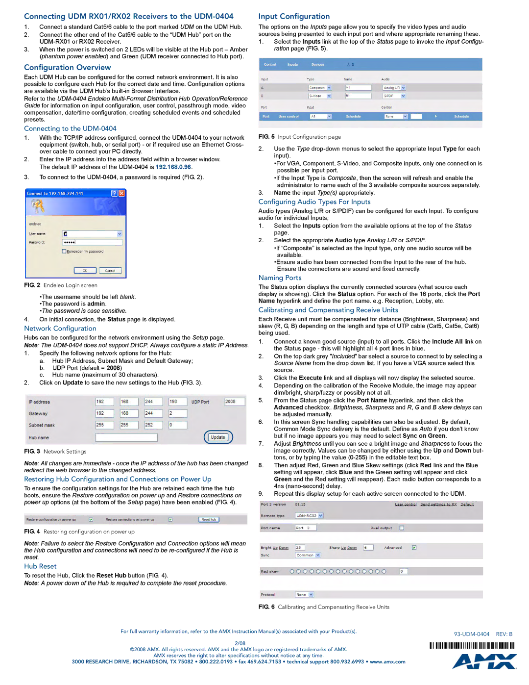
Calibrating and Compensating Receive Units
Each Receive unit must be compensated for distance (Brightness, Sharpness) and skew (R, G, B) depending on the length and type of UTP cable (Cat5, Cat5e, Cat6) being used.
1.Connect a known good source (input) to all ports. Click the Include All link on the Status page - this will highlight all 4 port lines in blue.
2.On the top dark grey "Included" bar select a source to connect to by selecting a Source Name from the drop down list. If you have a VGA source select this source.
3.Click the Execute link and all displays will now display the selected source.
4.Depending on the calibration of the Receive Module, the image may appear dim/bright, sharp/fuzzy or possibly not at all.
5.From the Status page click the Port Name hyperlink, and then click the Advanced checkbox. Brightness, Sharpness and R, G and B skew delays can be adjusted manually.
6.In this screen Sync handling capabilities can also be adjusted. By default, Common Mode Sync delivery is the default. Define as Auto if you don't know but if no image appears you may need to select Sync on Green.
7.Adjust Brightness until you can see a bright image and Sharpness to focus the image correctly. Values can be changed by either using the Up and Down but- tons, or by typing the value (0-255) in the editable text box.
8.Then adjust Red, Green and Blue Skew settings (click Red link and the Blue setting will appear, click Blue and the Green setting will appear and click Green and the Red setting will reappear). Each radio button corresponds to a 4ns (nano-second) delay.
9.Repeat this display setup for each active screen connected to the UDM.
FIG. 6 Calibrating and Compensating Receive Units