UG-065
USING THE BOARD
GETTING STARTED
The development board comes preprogrammed as a datalogger at a 100 Hz datarate. To log data, do the following:
1.Insert two AAA batteries into the battery holder.
2.Insert the MicroSD card into the slot. The card should be formatted with a FAT32 file system; most microSD cards come this way.
3.Push the on/off switch to the on position to power up the board. The red LED turns on, and the green LED blinks to indicate that the board is logging data.
4.When logging is completed, slide the on/off switch to the off position.
5.Remove the card from the slot and insert it into the card reader.
6.Insert the card reader into the USB port on your computer.
The acceleration log file is written to the path \XL345\DB0001.txt on the microSD card. The data in the text file consists of a set of
To plot the logged data using Microsoft Excel, download the XL345DB_DataPlotter.xls file from the ADXL345 product page and follow the instructions described in the file. Users are prompted to browse to their logged data file (DBxxxx.txt), the data is imported and plotted in a new workbook, and users are then prompted to save that workbook.
PROGRAMMING THE BOARD
The board can be repurposed with no programming required using the .hex files provided on the ADXL345 product page. The .hex files are uploaded onto the board using the ARMWSD program, which can be downloaded at ftp://ftp.analog.com/pub/MicroConverter/ARM%20Tools/AR MWSDv1.8.zip. Simply unzip the folder to a known location and open the ARMWSD.exe file to use the program. No installation is required.
To reprogram the board, use the cable provided with the board and follow these instructions:
1.Download the desired .hex file from the ADXL345 product page to a known location, or locate it on your machine.
2.Open ARMWSD.
3.Click Configure… (see Figure 3) and select the Parts tab, shown in see. Make sure the ADuC7024 is selected in the Select Part
Evaluation Board User Guide
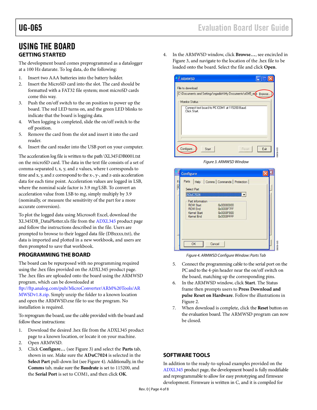
4.In the ARMWSD window, click Browse…, see encircled in Figure 3, and navigate to the location of the .hex file to be loaded onto the board. Select the file and click Open.
Figure 3. ARMWSD Window
Figure 4. ARMWSD Configure Window: Parts Tab
5.Connect the programming cable to the serial port on the PC and to the
6.In the ARMWSD window, click Start. The Status frame then prompts users to Press Download and pulse Reset on Hardware. Follow the illustrations in Figure 2.
7.When download is complete, click the Reset button on the evaluation board. The ARMWSD program can now be closed.
SOFTWARE TOOLS
In addition to the
Rev. 0 Page 4 of 8