Manuals
/
Antec
/
Household Appliance
/
Fan
Antec
ISK 100
user manual
Connecting The Front I/O Ports, 3.1 USB, 3.2 AC’97 / HD AUDIO PORTS
Models:
ISK 100
1
8
11
11
Download
11 pages
737 b
4
5
6
7
8
9
10
11
Install
Connecting The Front I/O Ports
Page 8
Image 8
Page 7
Page 9
Page 8
Image 8
Page 7
Page 9
Contents
USER’S MANUAL
ISK Series
TABLE OF CONTENTS
ISK 100 USER’S MANUAL
Case Type
The ISK 100 is powered by a 90-watt power adapter
HARDWARE INSTALLATION GUIDE
2.5” hard drives can be mounted to a bracket underneath the
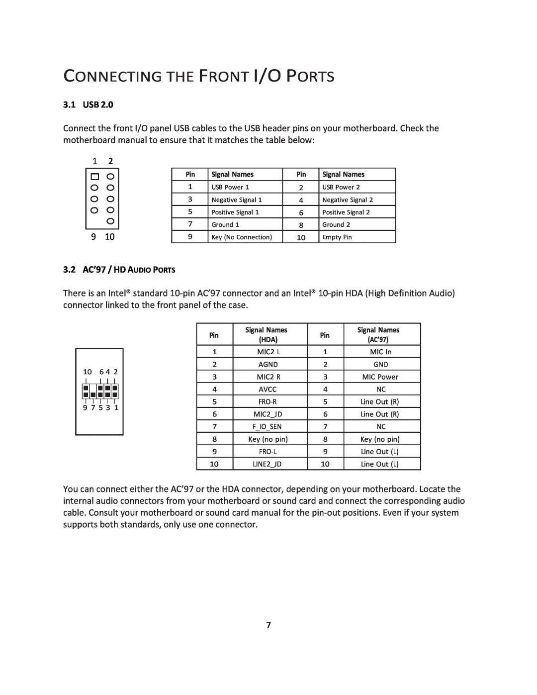
3.2 AC’97 / HD AUDIO PORTS
CONNECTING THE FRONT I/O PORTS
3.1 USB
Note Polarity positive and negative does not matter for switches
3.3 POWER SWITCH / RESET SWITCH / HARD DISK DRIVE LED CONNECTORS
3.4 REWIRING MOTHERBOARD HEADER CONNECTIONS
1. Replace the right side panel, securing it with the two screws
COOLING SYSTEM
Antec, Inc 47900 Fremont Blvd. Fremont, CA 94538 USA tel fax
Antec Europe B.V Stuttgartstraat 3047 AS Rotterdam Netherlands
tel +31 0 10 fax +31 0 10 Customer Support US & Canada 1-800-22ANTEC
customersupport@antec.com Europe +31 0 10
Top
Page
Image
Contents