Manuals
/
Antec
/
Computer Equipment
/
Power Supply
Antec
New Solution Series Connecting the USB Ports, Connecting the Audio Ports AC’ 97 and HDA
Models:
NSK2480
New Solution Series
1
4
8
8
Download
8 pages
21.09 Kb
1
2
3
4
5
6
7
8
Specs
Install
Signal Names
Setting Up
New Solution Series
Page 4
Image 4
Page 3
Page 5
Page 4
Image 4
Page 3
Page 5
Contents
New Solution Series
NSK2480
User’s Manual
Manuel de l’utilisateur Anwenderhandbuch Manuale per l’operatore
NSK Quiet Desktop Case The Power Supply
Setting Up
The Triple Chamber structure
New Solution Series User’s Manual
Installing the Motherboard
Connecting the Power and LED
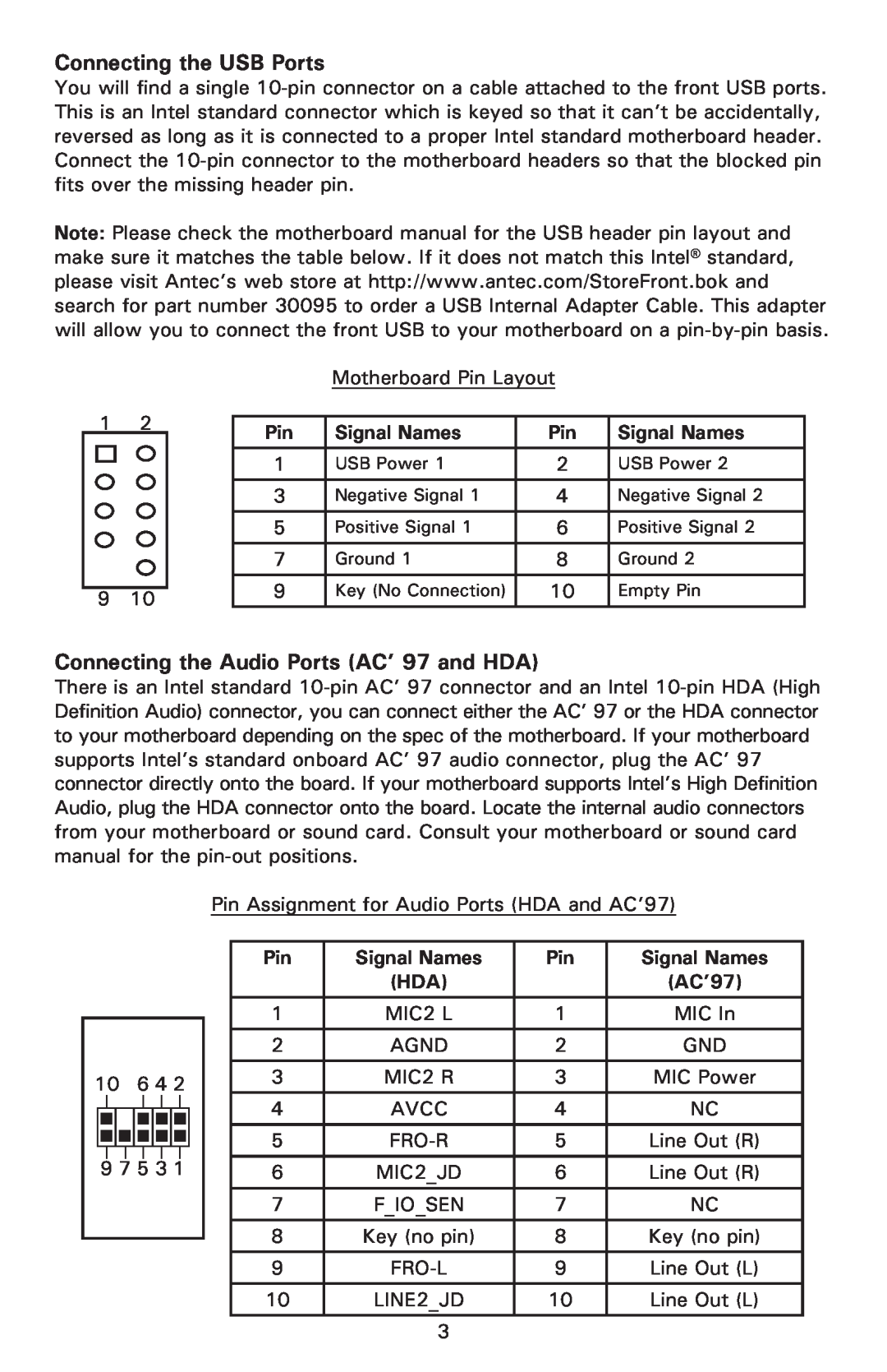
Connecting the USB Ports
Connecting the Audio Ports AC’ 97 and HDA
Signal Names
AC’97
5.25” Device Installation
Hard disk Drive Installation
Cooling System The 120mm TriCool fans
Note regarding using fan speed controllers with TriCool fans
Specifications
The Power Supply Air Intake
The Bottom Air Intake
80 PLUS certified power supplies
Learn more about 80 PLUS
Antec, Inc
Antec Europe B.V
Customer Support US & Canada
Europe
Top
Page
Image
Contents