1Connect Battery
For safety, the
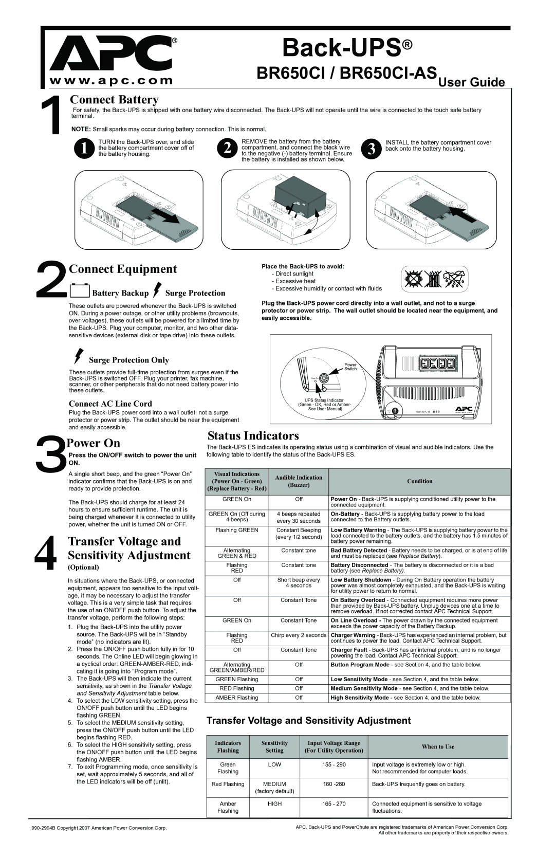
NOTE: Small sparks may occur during battery connection. This is normal.
1 | TURN the |
the battery compartment cover off of | |
the battery housing. | |
|
|
|
|
2 | REMOVE the battery from the battery | INSTALL the battery compartment cover |
compartment, and connect the black wire | 3 back onto the battery housing. | |
to the negative |
the battery is installed as shown below.
2Connect Equipment
Battery Backup  Surge Protection
Place the Back-UPS to avoid:
-Direct sunlight
-Excessive heat
-Excessive humidity or contact with fluids
These outlets are powered whenever the
Plug the
sensitive devices (external disk or tape drive) into these outlets. |
|
| |
Surge Protection Only |
| Power |
|
These outlets provide | Switch |
| |
|
| ||
Power On |
| ||
scanner, or other peripherals that do not need battery power into |
|
| |
these outlets. |
|
|
|
Connect AC Line Cord |
| UPS Status Indicator |
|
| (Green - OK, Red or Amber- |
| |
Plug the | See User Manual) | Power On | |
|
| ||
protector or power strip. The outlet should be near the equipment |
|
| |
and easily accessible. | Status Indicators |
| |
Power On |
| ||
The | |||
Press the ON/OFF switch to power the unit following table to identify the status of the |
| ||
3AON.single short beep, and the green “Power On” | Visual Indications | Audible Indication | Condition |
indicator confirms that the | (Power On - Green) | (Buzzer) | |
ready to provide protection. | (Replace Battery - Red) |
| |
|
| ||
The |
| GREEN On |
|
| Off | Power On - | ||||
|
|
|
|
|
|
| connected equipment. | |||
hours to ensure sufficient runtime. The unit is |
|
|
|
|
|
|
| |||
| GREEN On (Off during | 4 beeps repeated | ||||||||
being charged whenever it is connected to utility |
| |||||||||
| 4 beeps) |
| every 30 seconds | connected to the Battery outlets. | ||||||
power, whether the unit is turned ON or OFF. |
|
| ||||||||
|
|
|
|
|
|
|
|
|
| |
| Flashing GREEN |
| Constant Beeping | Low Battery Warning - The | ||||||
|
|
| ||||||||
Transfer Voltage and |
|
|
|
| (every 1/2 second) | load connected to the battery outlets, and the battery has 1.5 minutes of | ||||
|
|
|
|
|
|
| battery power remaining. | |||
|
|
|
|
|
|
|
| |||
Sensitivity Adjustment |
| Alternating |
| Constant tone | Bad Battery Detected - Battery needs to be charged, or is at end of life | |||||
| GREEN & RED |
|
|
|
| and must be replaced (see Replace Battery). | ||||
(Optional) |
| Flashing |
| Constant tone | Battery Disconnected - The battery is disconnected or it is a bad | |||||
4 In situations where the |
| RED |
|
|
|
| battery (see Replace Battery). | |||
| Off |
| Short beep every | Low Battery Shutdown - During On Battery operation the battery | ||||||
equipment, appears too sensitive to the input volt- |
|
|
|
| 4 seconds | power was almost completely exhausted, and the | ||||
|
|
|
|
|
|
| for utility power to return to normal. | |||
age, it may be necessary to adjust the transfer |
|
|
|
|
|
|
| |||
| Off |
| Constant Tone | On Battery Overload - Connected equipment requires more power | ||||||
voltage. This is a very simple task that requires |
|
| ||||||||
|
|
|
|
|
|
| than provided by | |||
the use of an ON/OFF push button. To adjust the |
|
|
|
|
|
|
| |||
|
|
|
|
|
|
| remove overload. If not corrected contact APC Technical Support. | |||
transfer voltage, perform the following steps: |
|
|
|
|
|
|
|
|
|
|
| GREEN On |
| Constant Tone | On Line Overload - The power drawn by the connected equipment | ||||||
1. Plug the |
|
|
|
|
|
|
| exceeds the power capacity of the Battery Backup. | ||
source. The |
| Flashing |
| Chirp every 2 seconds Charger Warning - | ||||||
mode” (no indicators are lit). |
| RED |
|
|
|
| continues to power the load. Contact APC Technical Support. | |||
2. Press the ON/OFF push button fully in for 10 |
| Off |
| Constant Tone | Charger Fault - | |||||
seconds. The Online LED will begin glowing in |
|
|
|
|
|
|
| powering the load. Contact APC Technical Support. | ||
a cyclical order: |
| Alternating |
|
| Off | Button Program Mode - see Section 4, and the table below. | ||||
cating it is going into “Program mode”. |
| GREEN/AMBER/RED |
|
|
|
|
|
| ||
3. The |
| GREEN Flashing |
|
| Off | Low Sensitivity Mode - see Section 4, and the table below. | ||||
sensitivity, as shown in the Transfer Voltage |
|
|
|
|
|
|
|
|
|
|
| RED Flashing |
|
| Off | Medium Sensitivity Mode - see Section 4, and the table below. | |||||
and Sensitivity Adjustment table below. |
|
|
| |||||||
|
|
|
|
|
|
|
|
|
| |
| AMBER Flashing |
|
| Off | High Sensitivity Mode - see Section 4, and the table below. | |||||
4. To select the LOW sensitivity setting, press the |
|
|
| |||||||
|
|
|
|
|
|
|
|
|
| |
ON/OFF push button until the LED begins |
|
|
|
|
|
|
|
|
|
|
flashing GREEN. |
| Transfer Voltage and Sensitivity Adjustment | ||||||||
5. To select the MEDIUM sensitivity setting, |
| |||||||||
press the ON/OFF push button until the LED |
|
|
|
|
|
|
|
|
|
|
begins flashing RED. |
|
|
|
|
|
|
|
|
|
|
| Indicators |
| Sensitivity |
| Input Voltage Range |
|
| |||
6. To select the HIGH sensitivity setting, press |
|
|
| When to Use |
| |||||
| Flashing |
|
| Setting |
| (For Utility Operation) |
| |||
the ON/OFF push button until the LED begins |
|
|
|
|
|
| ||||
flashing AMBER. |
|
|
|
|
|
|
|
|
|
|
| Green |
|
| LOW |
|
| 155 - 290 | Input voltage is extremely low or high. |
| |
7. To exit Programming mode, once sensitivity is |
|
|
|
|
|
| ||||
| Flashing |
|
|
|
|
|
| Not recommended for computer loads. |
| |
set, wait approximately 5 seconds, and all of |
|
|
|
|
|
|
|
| ||
|
|
|
|
|
|
|
|
|
| |
the LED indicators will be off (unlit). |
| Red Flashing |
| MEDIUM |
|
| 160 |
| ||
|
|
|
|
|
| |||||
|
|
| (factory default) |
|
|
|
|
| ||
|
|
|
|
|
|
|
|
|
|
|
|
| Amber |
|
| HIGH |
|
| 165 - 270 | Connected equipment is sensitive to voltage |
|
|
| Flashing |
|
|
|
|
|
| fluctuations. |
|
|
|
|
|
|
|
|
|
|
| |
|
|
|
|
| APC, | |||||
|
|
|
|
|
|
|
|
| All other trademarks are property of their respective owners. | |