1788a specifications
Aphex Systems 1788A is a high-performance microphone preamp and A/D converter known for its exceptional sound quality and versatility. This device is widely used in professional recording studios, broadcast facilities, and live sound applications, catering to a range of audio needs from vocals to instruments.One of the key features of the 1788A is its ability to handle a wide variety of microphone types, including dynamic, condenser, and ribbon microphones. It provides a significant amount of gain, with a range of up to 70dB, allowing it to capture even the faintest of sounds without introducing noise. The flexibility of input options is enhanced by phantom power, which can be activated for condenser mics needing external power.
The Aphex 1788A also integrates advanced A/D conversion technology, providing high-resolution 24-bit audio with sample rates up to 192 kHz. This ensures that audio fidelity is maintained during the recording process. The unit features a dual-path A/D converter, which optimizes the signal for clarity and precision.
The device also incorporates Aphex’s innovative iEqualization processing, allowing users to enhance their recordings with EQ capabilities in real time. The iEqualization feature is particularly beneficial for adjusting the tonal characteristics of the source material, providing a more polished final product.
Another standout characteristic of the Aphex 1788A is its robust build quality. Designed for the rigors of professional use, the unit is housed in a rugged chassis that can withstand the demands of mobile and studio environments alike.
Transporting this device is made easier due to its rack-mountable design, fitting seamlessly into any standard 19-inch rack setup. Additionally, users appreciate the intuitive front-panel controls that facilitate easy adjustments and monitoring of levels.
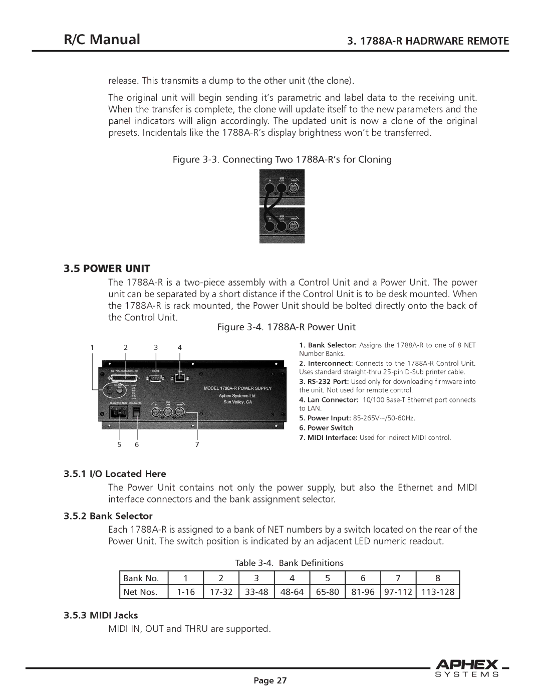
In terms of connectivity, the 1788A offers multiple outputs, including analog XLR and digital outputs via AES/EBU and S/PDIF connections, making it highly compatible with various audio interfaces and recording systems.
Overall, the Aphex Systems 1788A is a powerful tool that combines exceptional preamp performance with high-quality A/D conversion, making it an ideal choice for audio professionals seeking reliability and superior sound quality in their recordings. Its comprehensive feature set ensures it meets the demands of both studio and live environments, solidifying its reputation as a trusted piece of audio equipment.

