C H A P T E R 1
Hardware
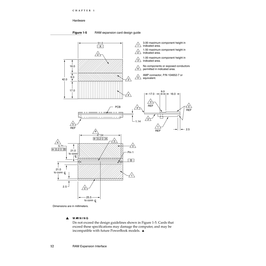
Figure 1-5 RAM expansion card design guide
16.0
9.0
42.0
51.0 | 1 | 3.00 maximum component height in |
- A - | indicated area. | |
| 2 | 1.50 maximum component height in |
2 | indicated area. | |
|
| |
| 3 | 1.00 maximum component height in |
| indicated area. | |
| 4 | No components or exposed conductors |
| permitted in indicated area. | |
| 5 | AMP connector, P/N |
| equivalent. | |
| 3 |
|
|
| 17.0 |
|
|
| 9.0 |
|
|
|
| 4 | 17.0 | 16.0 |
|
|
|
|
|
| |
|
|
|
|
| 3 |
|
|
|
| PCB |
| REF |
|
|
|
|
| 4 |
| |
|
|
|
|
|
| |
|
|
|
|
| 3 |
|
|
| 5 |
|
| 1.14 |
|
|
|
|
|
| 1 | |
|
| REF |
|
|
| |
|
|
|
|
| REF | |
|
| 4 |
|
|
| |
|
| 47.54 |
|
|
|
|
|
| 0.2 S | A |
|
|
|
4 |
|
| 5 |
|
|
|
|
|
|
|
|
| |
5.71 |
|
| 3 |
|
| |
0.2 S | B | 21.0 |
| Pin 1 |
|
|
|
|
|
|
| ||
|
| to conn |
|
|
| |
|
|
|
|
|
| |
|
| C |
|
|
|
|
|
| L |
|
|
|
|
|
|
|
| - B - |
|
|
21.0 |
|
|
|
|
|
|
to conn C |
|
|
|
|
| |
| L |
|
| 1 |
|
|
|
|
|
|
|
| |
| 2.5 | 2 |
|
|
|
|
|
|
|
|
|
| |
|
| 25.5 |
|
|
|
|
|
| to conn C |
|
|
|
|
|
| L |
|
|
|
|
2
REF
2.5
Dimensions are in millimeters.
▲W AR N I N G
Do not exceed the design guidelines shown in Figure
12 | RAM Expansion Interface |