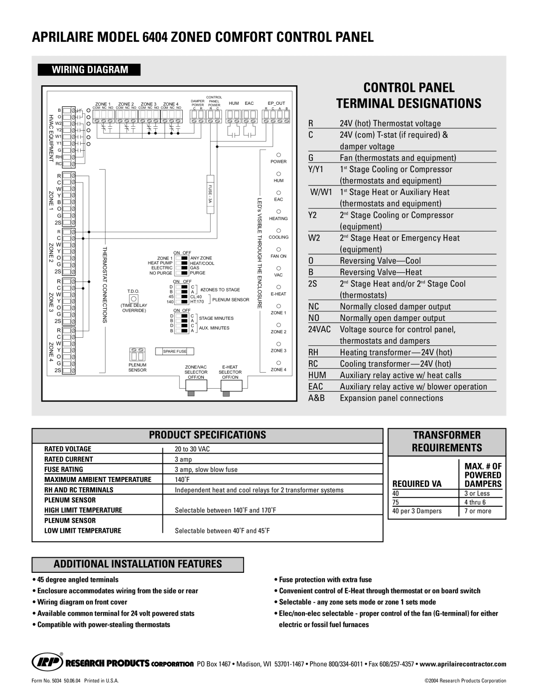
Aprilaire 6404 Max. # Of, Powered, Required Va, Dampers, Control Panel Terminal Designations

Models: 6404

1 2
Download 2 pages 40.38 Kb
Page 2
Image 2
APRILAIRE MODEL 6404 ZONED COMFORT CONTROL PANEL

APRILAIRE MODEL 6404 ZONED COMFORT CONTROL PANEL

WIRING DIAGRAM


CONTROL


ZONE 1

ZONE 2

ZONE 3

ZONE 4

DAMPER

PANEL

HUM

EAC


EP_OUT


POWER

POWER

R

B


COM NC NO COM NC NO COM NC NO COM NC NO

C R

R C


C A

HVAC

B


O


W2


EQUIPMENT

Y2


W1


Y1


G


RH


RC


POWER


R


HUM


C


ZONE1


FUSE -3A


LED’s


O


W


Y


EAC


B


VISIBLE


R


G


HEATING

ZONE 2 ZONE3

2S

THERMOSTATCONNECTIONS


THROUGH THEENCLOSURE


2S

B

A


COOLING


C


W


Y


ON OFF


FAN ON


O


ZONE 1

ANY ZONE


G


HEAT PUMP

HEAT/COOL


2S


ELECTRIC

GAS


NO PURGE

PURGE


VAC


R


ON OFF


C

T.D.O.

D

C

#ZONES TO STAGE


W

B

A


E-HEAT


45

CL:40

PLENUM SENSOR


Y


(TIME DELAY

140

HT:170


O


OVERRIDE)


ON OFF


ZONE 1


G


D

C

STAGE MINUTES


R


D

C

AUX. MINUTES


ZONE 2


B

A


C


ZONE

W


Y


SPARE FUSE


ZONE 3


4

O


G

PLENUM


ZONE/VAC

E-HEAT


ZONE 4


2S

SENSOR


SELECTOR

SELECTOR


OFF/ON

OFF/ON


CONTROL PANEL

TERMINAL DESIGNATIONS

R24V (hot) Thermostat voltage

C 24V (com) T-stat (if required) & damper voltage

G Fan (thermostats and equipment)

Y/Y1

1st Stage Cooling or Compressor


(thermostats and equipment)

W/W1

1st Stage Heat or Auxiliary Heat


(thermostats and equipment)

Y2

2nd Stage Cooling or Compressor


(equipment)

W2

2nd Stage Heat or Emergency Heat


(equipment)

OReversing Valve—Cool

B Reversing Valve—Heat

2S 2nd Stage Heat and/or 2nd Stage Cool (thermostats)

NC

Normally closed damper output

NO

Normally open damper output

24VAC

Voltage source for control panel,


thermostats and dampers

RH

Heating transformer — 24V (hot)

RC

Cooling transformer — 24V (hot)

HUM

Auxiliary relay active w/ heat calls

EAC

Auxiliary relay active w/ blower operation

A&B

Expansion panel connections

PRODUCT SPECIFICATIONS


RATED VOLTAGE


20 to 30 VAC


RATED CURRENT


3 amp


FUSE RATING


3 amp, slow blow fuse


MAXIMUM AMBIENT TEMPERATURE


140˚F


RH AND RC TERMINALS


Independent heat and cool relays for 2 transformer systems


PLENUM SENSOR


HIGH LIMIT TEMPERATURE


Selectable between 140˚F and 170˚F


PLENUM SENSOR


LOW LIMIT TEMPERATURE


Selectable between 40˚F and 45˚F


TRANSFORMER

REQUIREMENTS


MAX. # OF


POWERED

REQUIRED VA

DAMPERS

40

3 or Less

75

4 thru 6

40 per 3 Dampers

7 or more


ADDITIONAL INSTALLATION FEATURES

• 45 degree angled terminals

• Fuse protection with extra fuse

• Enclosure accommodates wiring from the side or rear

• Convenient control of E-Heat through thermostat or on board switch

• Wiring diagram on front cover

• Selectable - any zone sets mode or zone 1 sets mode

• Available common terminal for 24 volt powered stats

Elec/non-elec selectable - proper control of the fan (G-terminal) for either

• Compatible with power-stealing thermostats

electric or fossil fuel furnaces

WIRING DIAGRAMCONTROL PANELPRODUCT SPECIFICATIONSTRANSFORMERMAX. # OFPOWEREDREQUIRED VADAMPERSADDITIONAL INSTALLATION FEATURESManual backgroundManual backgroundManual backgroundManual backgroundManual background PO Box 1467 • Madison, WI 53701-1467 • Phone 800/334-6011 • Fax 608/257-4357www.aprilairecontractor.com

Form No. 5034 50.06.04 Printed in U.S.A.

©2004 Research Products Corporation

Page 2
Image 2
Aprilaire Max. # Of, Powered, Required Va, Dampers, APRILAIRE MODEL 6404 ZONED COMFORT CONTROL PANEL, Wiring Diagram