6202/6203 MODELINSTALLATIONINSTRUCTIONS
SAFETY INSTRUCTIONS
Read this Installation Manual before beginning installation of the Aprilaire Zoned Comfort Control System.
For questions call Research Products Corporation at (800) 334-6011.
WARNING
1.120 Volts may cause serious injury from electrical shock. Sudden operation may cause serious injury from moving parts. Leave power disconnected until installation is complete.
2.Sharp edges may cause serious injury from cuts. Use care when making duct openings and handling ductwork.
3.The Aprilaire Zoned Comfort Control System is designed for indoor use only. Do not expose any component of the zone control system to moisture. Do not mount any Aprilaire Zoned Comfort Control equipment where it may be accessible to children.
CAUTION
1.Installation must be done in accordance with all applicable codes.
2.Installer should touch a grounded metal object before handling the Aprilaire control panel to avoid potential loss of internal computer programs due to static discharge.
3.A zoned comfort control system may not control temperature properly unless the heating and cooling system is properly sized and balanced.
4.Insufficient airflow or excessive temperatures through the heating and cooling system could result in equipment damage. Refer to the manufacturer’s recommendations for minimum safe airflow and temperature requirements.
5.Excessive pressure across a bypass evaporative type humidifier may cause high air velocity in the humidifier, resulting in water being blown into the ductwork. Refer to the Design Guide for humidifier installation instructions.
6.Install an outdoor thermostat to prevent non-seasonal equipment starts if using auto changeover thermostats.
7.Do not mount the control panel on any part of the heating/cooling equipment or ductwork.
8.Do not install control panel where temperatures exceed 158°F (70°C), or drop below freezing (32°F).
INSTALLATION | | | |
CAUTION: Installer must touch a grounded metal object before handling the Aprilaire Zoned | | MOUNTING HOLE | ENCLOSURE BASE |
Comfort Control panel to avoid potential loss of programs due to static discharge. | | 2 PLACES |
| |
| | |
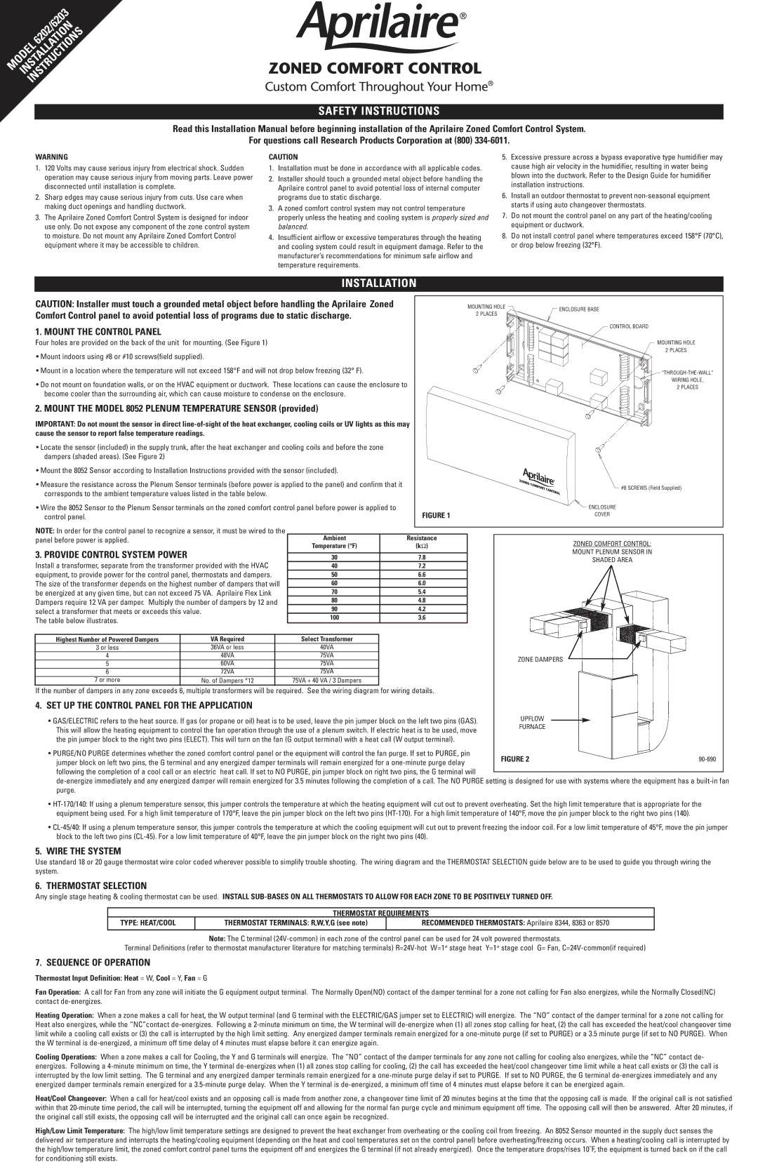
1. MOUNT THE CONTROL PANEL | | | CONTROL BOARD |
| | |
Four holes are provided on the back of the unit for mounting. (See Figure 1) | | | MOUNTING HOLE |
• Mount indoors using #8 or #10 screws(field supplied). | | | 2 PLACES |
| | |
• Mount in a location where the temperature will not exceed 158°F and will not drop below freezing (32° F). | | | “THROUGH-THE-WALL” |
• Do not mount on foundation walls, or on the HVAC equipment or ductwork. These locations can cause the enclosure to | | | WIRING HOLE, |
| | 2 PLACES |
become cooler than the surrounding air, which can cause moisture to condense on the enclosure. | | | |
2. MOUNT THE MODEL 8052 PLENUM TEMPERATURE SENSOR (provided) | | | |
IMPORTANT: Do not mount the sensor in direct line-of-sight of the heat exchanger, cooling coils or UV lights as this may | | | |
cause the sensor to report false temperature readings. | | | |
• Locate the sensor (included) in the supply trunk, after the heat exchanger and cooling coils and before the zone | | | |
dampers (shaded areas). (See Figure 2) | | | |
• Mount the 8052 Sensor according to Installation Instructions provided with the sensor (included). | | | |
• Measure the resistance across the Plenum Sensor terminals (before power is applied to the panel) and confirm that it | | | #8 SCREWS (Field Supplied) |
corresponds to the ambient temperature values listed in the table below. | | |
| | |
• Wire the 8052 Sensor to the Plenum Sensor terminals on the zoned comfort control panel before power is applied to | FIGURE 1 | | ENCLOSURE |
control panel. | | COVER |
| |
NOTE: In order for the control panel to recognize a sensor, it must be wired to the | | | | |
panel before power is applied. | | | Ambient | Resistance | | ZONED COMFORT CONTROL: |
| | | | Temperature (°F) | (kΩ) | |
3. PROVIDE CONTROL SYSTEM POWER | | | | MOUNT PLENUM SENSOR IN |
| | | | |
| | 30 | 7.8 | |
| | | SHADED AREA |
Install a transformer, separate from the transformer provided with the HVAC | 40 | 7.2 | |
| |
equipment, to provide power for the control panel, thermostats and dampers. | 50 | 6.6 | | |
The size of the transformer depends on the highest number of dampers that will | 60 | 6.0 | | |
be energized at any given time, but can not exceed 75 VA. Aprilaire Flex Link | 70 | 5.4 | | |
Dampers require 12 VA per damper. Multiply the number of dampers by 12 and | 80 | 4.8 | | |
select a transformer that meets or exceeds this value. | 90 | 4.2 | | |
100 | 3.6 | | |
The table below illustrates. | | | | |
| | | | | | | |
Highest Number of Powered Dampers | | VA Required | | Select Transformer | | | |
3 or less | | 36VA or less | | 40VA | | | |
4 | | 48VA | | 75VA | | | ZONE DAMPERS |
5 | | 60VA | | 75VA | | |
| | | | |
6 | | 72VA | | 75VA | | | |
7 or more | | No. of Dampers *12 | | 75VA + 40 VA / 3 Dampers | | | |
If the number of dampers in any zone exceeds 6, multiple transformers will be required. See the wiring diagram for wiring details.
| 4. SET UP THE CONTROL PANEL FOR THE APPLICATION | | | |
| • GAS/ELECTRIC refers to the heat source. If gas (or propane or oil) heat is to be used, leave the pin jumper block on the left two pins (GAS). | UPFLOW | | |
| | |
| This will allow the heating equipment to control the fan operation through the use of a plenum switch. If electric heat is to be used, move | FURNACE | | |
| | | |
| the pin jumper block to the right two pins (ELECT). This will turn on the fan (G output terminal) with a heat call (W output terminal). | | | |
| • PURGE/NO PURGE determines whether the zoned comfort control panel or the equipment will control the fan purge. If set to PURGE, pin | FIGURE 2 | 90-690 |
| jumper block on left two pins, the G terminal and any energized damper terminals will remain energized for a one-minute purge delay |
| | | |
| following the completion of a cool call or an electric heat call. If set to NO PURGE, pin jumper block on right two pins, the G terminal will | | | |
| | | |
de-energize immediately and any energized damper will remain energized for 3.5 minutes following the completion of a call. The NO PURGE setting is designed for use with systems where the equipment has a built-in fan purge.
•HT-170/140: If using a plenum temperature sensor, this jumper controls the temperature at which the heating equipment will cut out to prevent overheating. Set the high limit temperature that is appropriate for the equipment being used. For a high limit temperature of 170°F, leave the pin jumper block on the left two pins (HT-170). For a high limit temperature of 140°F, move the pin jumper block to the right two pins (140).
•CL-45/40: If using a plenum temperature sensor, this jumper controls the temperature at which the cooling equipment will cut out to prevent freezing the indoor coil. For a low limit temperature of 45°F, move the pin jumper block to the left two pins (CL-45). For a low limit temperature of 40°F, leave the pin jumper block on the right two pins (40).
5.WIRE THE SYSTEM
Use standard 18 or 20 gauge thermostat wire color coded wherever possible to simplify trouble shooting. The wiring diagram and the THERMOSTAT SELECTION guide below are to be used to guide you through wiring the system.
6. THERMOSTAT SELECTION
Any single stage heating & cooling thermostat can be used. INSTALL SUB-BASES ON ALL THERMOSTATS TO ALLOW FOR EACH ZONE TO BE POSITIVELY TURNED OFF.
THERMOSTAT REQUIREMENTS
TYPE: HEAT/COOL
THERMOSTAT TERMINALS: R,W,Y,G (see note)
RECOMMENDED THERMOSTATS: Aprilaire 8344, 8363 or 8570
Note: The C terminal (24V-common) in each zone of the control panel can be used for 24 volt powered thermostats.
Terminal Definitions (refer to thermostat manufacturer literature for matching terminals) R=24V-hot W=1st stage heat Y=1st stage cool G= Fan, C=24V-common(if required)
7. SEQUENCE OF OPERATION
Thermostat Input Definition: Heat = W, Cool = Y, Fan = G
Fan Operation: A call for Fan from any zone will initiate the G equipment output terminal. The Normally Open(NO) contact of the damper terminal for a zone not calling for Fan also energizes, while the Normally Closed(NC) contact de-energizes.
Heating Operation: When a zone makes a call for heat, the W output terminal (and G terminal with the ELECTRIC/GAS jumper set to ELECTRIC) will energize. The “NO” contact of the damper terminal for a zone not calling for Heat also energizes, while the “NC”contact de-energizes. Following a 2-minute minimum on time, the W terminal will de-energize when (1) all zones stop calling for heat, (2) the call has exceeded the heat/cool changeover time limit while a cooling call exists or (3) the call is interrupted by the high limit setting. Any energized damper terminals remain energized for a one-minute purge (if set to PURGE) or a 3.5 minute purge (if set to NO PURGE). When the W terminal is de-energized, a minimum off time delay of 4 minutes must elapse before it can energize again.
Cooling Operations: When a zone makes a call for Cooling, the Y and G terminals will energize. The “NO” contact of the damper terminals for any zone not calling for cooling also energizes, while the “NC” contact de- energizes. Following a 4-minute minimum on time, the Y terminal de-energizes when (1) all zones stop calling for cooling, (2) the call has exceeded the heat/cool changeover time limit while a heat call exists or (3) the call is interrupted by the low limit setting. The G terminal and any energized damper terminals remain energized for a one-minute purge delay if set to PURGE. If set to NO PURGE, the G terminal de-energizes immediately and any energized damper terminals remain energized for a 3.5-minute purge delay. When the Y terminal is de-energized, a minimum off time of 4 minutes must elapse before it can be energized again.
Heat/Cool Changeover: When a call for heat/cool exists and an opposing call is made from another zone, a changeover time limit of 20 minutes begins at the time that the opposing call is made. If the original call is not satisfied within that 20-minute time period, the call will be interrupted, turning the equipment off and allowing for the normal fan purge cycle and minimum equipment off time. The opposing call will then be answered. After 20 minutes, if the original call still exists, the opposing call will be interrupted and the original call can once again be recognized.
High/Low Limit Temperature: The high/low limit temperature settings are designed to prevent the heat exchanger from overheating or the cooling coil from freezing. An 8052 Sensor mounted in the supply duct senses the delivered air temperature and interrupts the heating/cooling equipment (depending on the heat and cool temperatures set on the control panel) before overheating/freezing occurs. When a heating/cooling call is interrupted by the high/low temperature limit, the zoned comfort control panel turns the equipment off and energizes the G terminal (if not already energized). Once the temperature drops/rises 10˚F, the equipment is turned back on if the call for conditioning still exists.