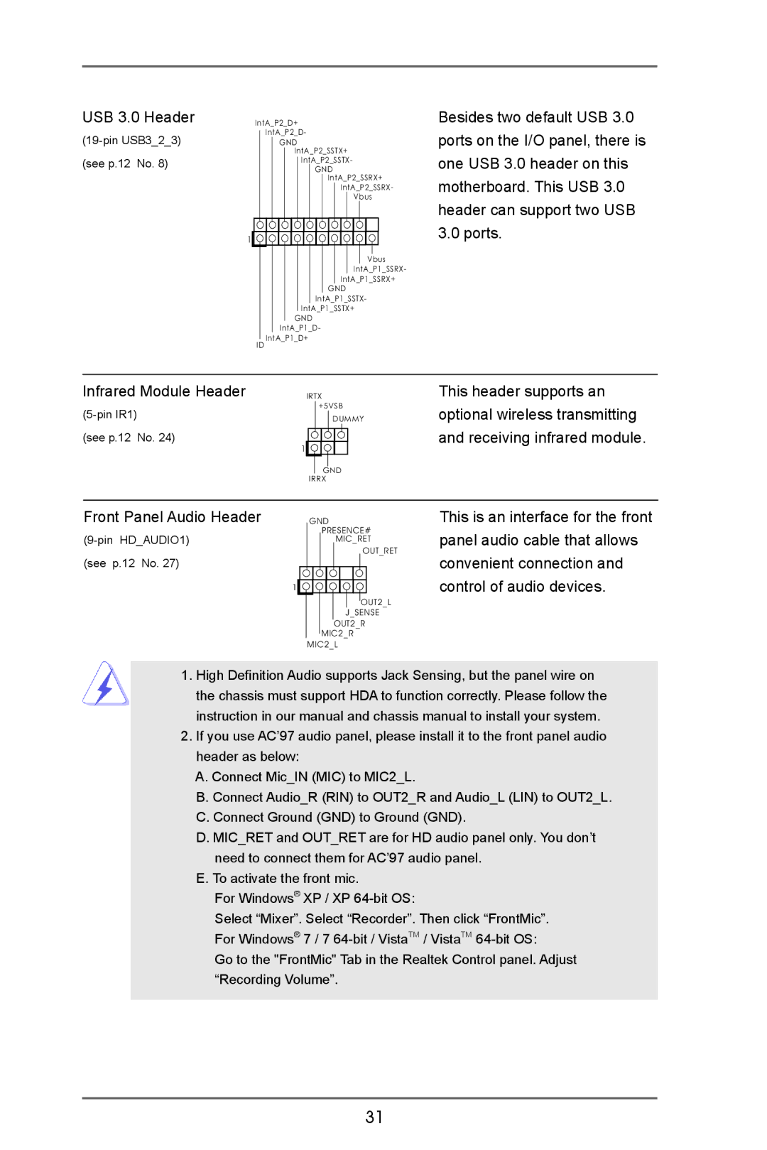
USB 3.0 Header |
| IntA_P2_D+ | ||||||||||||||||||||
|
| IntA_P2_D- | ||||||||||||||||||||
|
| |||||||||||||||||||||
|
|
|
|
| GND | |||||||||||||||||
|
|
|
|
|
|
|
| IntA_P2_SSTX+ | ||||||||||||||
(see p.12 No. 8) |
|
|
|
|
|
|
|
| IntA_P2_SSTX- | |||||||||||||
|
|
|
|
|
|
|
|
|
|
| GND | |||||||||||
|
|
|
|
|
|
|
|
|
|
|
|
| IntA_P2_SSRX+ | |||||||||
|
|
|
|
|
|
|
|
|
|
|
|
|
|
|
| IntA_P2_SSRX- | ||||||
|
|
|
|
|
|
|
|
|
|
|
|
|
|
|
|
|
| Vbus | ||||
| 1 |
|
|
|
|
|
|
|
|
|
|
|
|
|
|
|
|
|
|
|
|
|
|
|
|
|
|
|
|
|
|
|
|
|
|
|
|
|
|
|
|
|
|
| |
|
|
|
|
|
|
|
|
|
|
|
|
|
|
|
|
|
|
|
|
|
| |
|
|
|
|
|
|
|
|
|
|
|
|
|
|
|
|
|
|
|
|
|
| |
|
|
|
|
|
|
|
|
|
|
|
|
|
|
|
|
|
|
|
| Vbus | ||
|
|
|
|
|
|
|
|
|
|
|
|
|
|
|
|
|
| IntA_P1_SSRX- | ||||
|
|
|
|
|
|
|
|
|
|
|
|
|
|
|
| IntA_P1_SSRX+ | ||||||
|
|
|
|
|
|
|
|
|
|
|
|
|
| GND | ||||||||
|
|
|
|
|
|
|
|
|
|
| IntA_P1_SSTX- | |||||||||||
|
|
|
|
|
|
|
|
| IntA_P1_SSTX+ | |||||||||||||
|
|
|
|
|
|
|
| GND | ||||||||||||||
|
|
|
|
|
| IntA_P1_D- | ||||||||||||||||
|
|
| IntA_P1_D+ | |||||||||||||||||||
|
|
| ||||||||||||||||||||
|
| ID | ||||||||||||||||||||
Besides two default USB 3.0 ports on the I/O panel, there is one USB 3.0 header on this motherboard. This USB 3.0 header can support two USB 3.0 ports.
Infrared Module Header | IRTX |
+5VSB | |
DUMMY | |
(see p.12 No. 24) |
|
| 1 |
| GND |
| IRRX |
This header supports an optional wireless transmitting and receiving infrared module.
Front Panel Audio Header |
|
| GND | |||||||||
|
|
|
| PRESENCE# | ||||||||
|
|
|
|
|
| MIC_RET | ||||||
|
|
|
|
|
|
|
|
|
|
| OUT_RET | |
(see p.12 No. 27) | 1 |
|
|
|
|
|
|
|
|
|
|
|
|
|
|
|
|
|
|
|
|
|
|
| |
|
|
|
|
|
|
|
|
|
|
|
| |
|
|
|
|
|
|
|
|
|
|
| OUT2_L | |
|
|
|
|
|
|
|
| J_SENSE | ||||
|
|
|
|
|
|
| OUT2_R | |||||
|
|
|
|
| MIC2_R | |||||||
|
|
| MIC2_L | |||||||||
This is an interface for the front panel audio cable that allows convenient connection and control of audio devices.
1.High Definition Audio supports Jack Sensing, but the panel wire on the chassis must support HDA to function correctly. Please follow the instruction in our manual and chassis manual to install your system.
2.If you use AC’97 audio panel, please install it to the front panel audio header as below:
A.Connect Mic_IN (MIC) to MIC2_L.
B.Connect Audio_R (RIN) to OUT2_R and Audio_L (LIN) to OUT2_L.
C.Connect Ground (GND) to Ground (GND).
D.MIC_RET and OUT_RET are for HD audio panel only. You don’t need to connect them for AC’97 audio panel.
E.To activate the front mic.
For Windows® XP / XP
Select “Mixer”. Select “Recorder”. Then click “FrontMic”. For Windows® 7 / 7
Go to the "FrontMic" Tab in the Realtek Control panel. Adjust “Recording Volume”.
31