|
|
| |
1 | PIN | Signal Name | |
| 1 | LOUT L | |
(see p.10, No. 32) |
| 2 | AGND |
|
| 3 | LOUT R |
|
| 4 | LOUT JD |
|
|
|
|
|
|
| |
1 | PIN | Signal Name | |
| 1 | MIC L | |
(see p.10, No. 33) |
| 2 | AGND |
|
| 3 | MIC R |
|
| 4 | MIC JD |
|
|
|
|
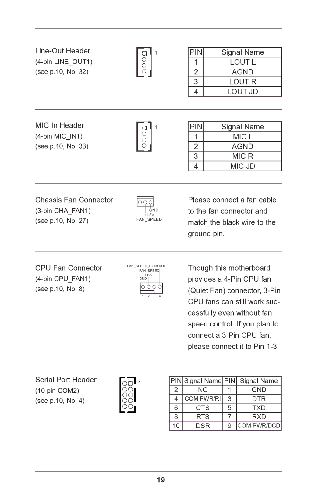
Chassis Fan Connector
(see p.10, No. 27)
![]() GND +12V
GND +12V
FAN_SPEED
Please connect a fan cable to the fan connector and match the black wire to the ground pin.
CPU Fan Connector
(see p.10, No. 8)
FAN_SPEED_CONTROL
FAN_SPEED
+12V GND
1 2 3 4
Though this motherboard provides a
Serial Port Header
1 | PIN | Signal Name | PIN | Signal Name |
| 2 | NC | 1 | GND |
| 4 | COM PWR/RI | 3 | DTR |
| 6 | CTS | 5 | TXD |
| 8 | RTS | 7 | RXD |
| 10 | DSR | 9 | COM PWR/DCD |
19