
IMB-770 specifications
The ASRock IMB-770 is a powerful and versatile industrial motherboard designed to meet the demands of a wide array of applications, ranging from industrial automation to embedded systems. This motherboard is built around the Intel 7th and 6th Generation Core processors, also known as Kaby Lake and Skylake, which provide exceptional performance and energy efficiency. With support for both the LGA 1151 socket, the IMB-770 is ideal for users looking to leverage the latest in Intel technology.One of the standout features of the ASRock IMB-770 is its rugged design, built to withstand the rigors of industrial environments. The motherboard supports a wide operating temperature range, from -20°C to +70°C, ensuring reliable performance even in extreme conditions. This durability is further enhanced by the board’s durable components, which are designed to operate continuously without failure.
The IMB-770 supports up to 64GB of DDR4 memory across four DIMM slots, offering robust memory capabilities necessary for multitasking and running complex applications. The extensive memory options make it suitable for demanding tasks such as data processing, image processing, and other memory-intensive operations.
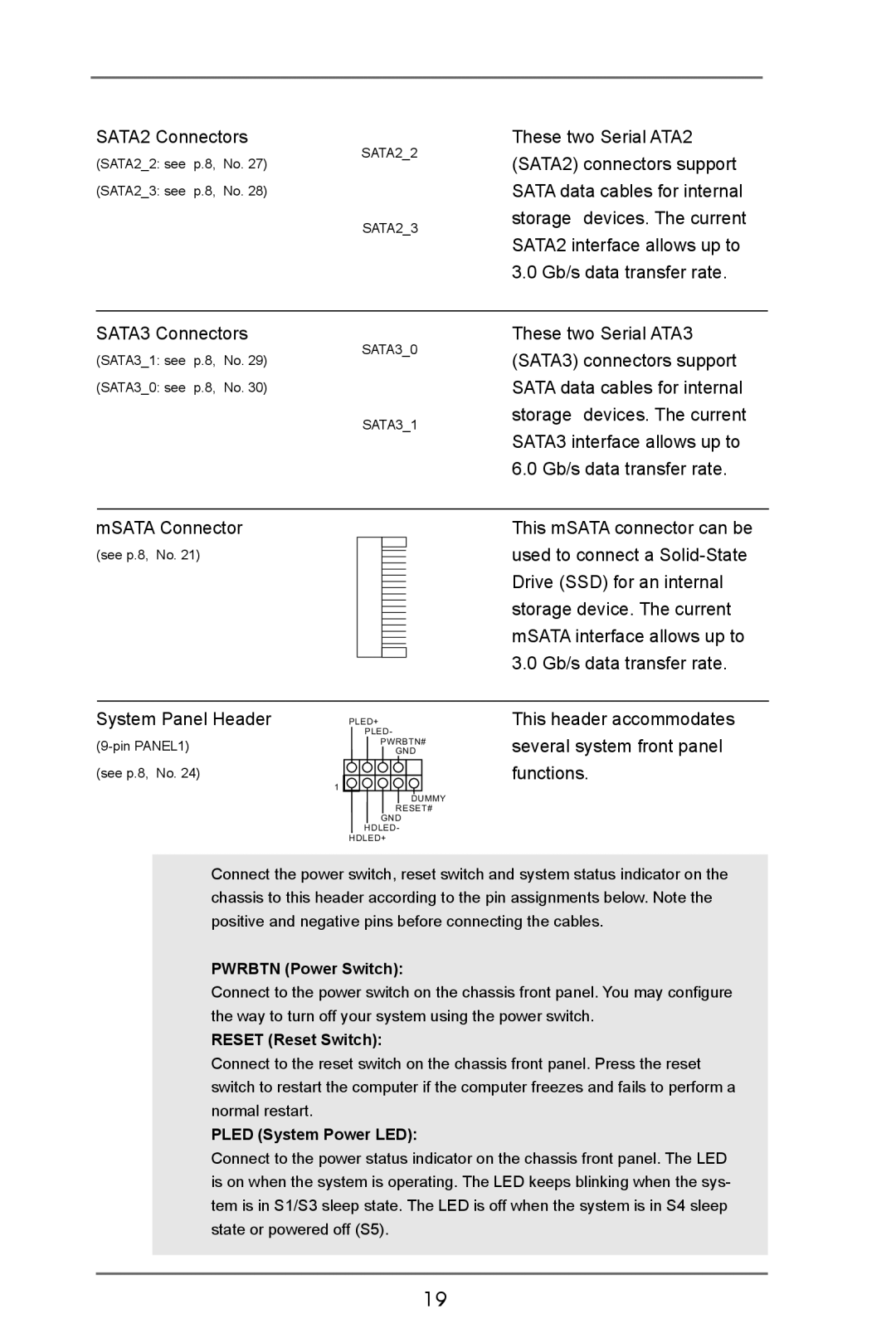
In terms of storage, the ASRock IMB-770 is equipped with multiple SATA III ports, allowing for high-speed data transfer rates. It also supports mSATA and M.2 interfaces, accommodating the latest solid-state drives for faster access and improved performance. This flexibility ensures that users can choose the storage solutions that best fit their requirements.
Connectivity is another area where the IMB-770 excels. It features dual Gigabit Ethernet ports for enhanced network redundancy and reliability. Furthermore, the motherboard boasts several USB 3.0 and USB 2.0 ports, allowing for the connection of a variety of peripherals. The integrated HDMI and DisplayPort outputs enable high-resolution video output, making the IMB-770 suitable for multimedia applications.
Another notable technology employed in the ASRock IMB-770 is the support for Intel's Trusted Execution Technology, which enhances security by protecting against malware and unauthorized access. This feature is crucial for industrial applications where data integrity and security are paramount.
Overall, the ASRock IMB-770 offers a robust set of features and technologies tailored for industrial and embedded applications. Its combination of performance, reliability, and security makes it an excellent choice for developers and engineers looking to deploy systems in demanding environments. With the IMB-770, users can build high-performance solutions that are both reliable and secure.