Infringe
Copyright Notice
Page
USB3
Motherboard Layout
No. Description
Panel
Speed LED Status Description
Off No Link Blinking Data Activity
Introduction
Package Contents
Specifications
Audio
Graphics
Storage
Connector
Feature
Rear Panel
Certifica
Support
Hardware
Monitor
English
ASRock A-Tuning
Unique Features
ASRock Uefi System Browser
ASRock Easy Driver Installer
ASRock FAN-Tastic Tuning
Installation
Installing the CPU
English
English
Installing the CPU Fan and Heatsink
Dual Channel Memory Configuration
Installing Memory Modules Dimm
English
PCI slot
Expansion Slots PCI and PCI Express Slots
Jumpers Setup
Default
See p.1, No
System Panel Header Pin PANEL1 See p.1, No
Onboard Headers and Connectors
To indicate the system’s
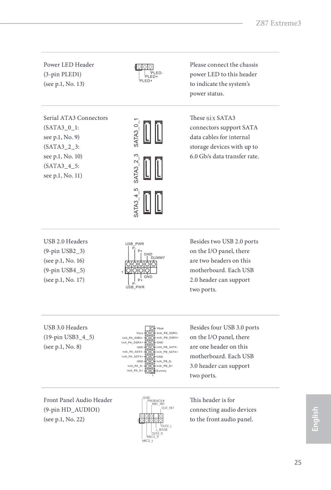
Power LED Header Please connect the chassis Pin PLED1
Power LED to this header
Power status
Header with a cable
Spdif Out Connector Please connect Pin SPDIFOUT1
Chassis Speaker Header
Pin SPEAKER1 Speaker to this header See p.1, No
This COM1 header supports a serial port module
CPU Fan Connectors Pin CPUFAN1 See p.1, No
Lieferumfang
Einleitung
Technische Daten
Grafikkarte
Rückblende
Anschluss
Funktion
Zertifizierungen
Support-CD
Überwachung
Betriebssystem
Deutsch
Jumpereinstellung
Standard Cmos löschen
Siehe S , Nr
Systemblende-Stiftleiste Polig, PANEL1 Siehe S , Nr
Integrierte Stiftleisten und Anschlüsse
Betrieb-LED-Stiftleiste Polig, PLED1 Siehe S , Nr
USB 2.0-Stiftleisten Polig, USB23 Siehe S , Nr Polig, USB45
Audiostiftleiste Frontblende
SPDIF-Ausgang Polig, SPDIFOUT1 Siehe S , Nr
Bitte verbinden Sie den
Polig, SPEAKER1
Dieser Stiftleiste
Und Empfangen
Infrarotmodul-Stiftleiste
Diese Stiftleiste unterstützt
Polig, IR1 Ein optionales kabelloses Siehe S , Nr
Contenu de l’emballage
Spécifications
Réseau
Stockage
Connectique
Du panneau
Arrière
Système
CD inclus
Surveillance
Du matériel
Français
Configuration des cavaliers jumpers
PANNEAU1 à 9 broches Voir p.1, No
Embases et connecteurs de la carte mère
Embase du panneau
Système
Embase LED ’alimentation PLED1 à 3 broches Voir p.1, No
Voir p.1, No Maximal de 6,0 Go/s
Embases USB
Embase du haut-parleur
Du châssis Parleur du châssis sur SPEAKER1 à 4 broches
Cette embase
Réception infrarouge optionnel
Embase pour module
Infrarouge
IR1 à 5 broches
Contenuto della confezione
Introduzione
Slot di
Specifiche
Piattaforma
Memoria
Grafica
Connettore
Pannello
Posteriore
Archiviazione
CD di
Supporto
Certificazioni
Italiano
Impostazione jumper
Header sul pannello del sistema
Header e connettori sulla scheda
SATA3 supportano cavi
Trasferimento dati fino a
Gb/s
Header altoparlante
Chassis Dello chassis a questo SPEAKER1 a 4 pin
Header
Un modulo infrarossi di
Header modulo infrarossi
Questo header supporta
IR1 a 5 pin
Contenido del paquete
Introducción
Especificaciones
Gráficos
Namiento
Cas del Bios
Panel trasero
Almace
CD de soporte
Monitor del
Certificaciones
Español
Predeterminado Borrado de Cmos
Instalación de los puentes
Corto
Puente de borrado de
Cabezal del panel del sistema
Conectores y cabezales incorporados
Cabezales USB
PLED1 de 3 pines
Consulte la pág.1, N.º Conectores Serie ATA3 SATA301
Consulte la pág.1, N.º SATA323
Spdifout de una
Cabezal de altavoces del
Chasis
SPEAKER1 de 4 pines
IR1 de 5 pines
Cabezal de módulo
Este cabezal admite un
Infrarrojo
Комплект поставки
Введение
Спецификация
Аудио
На задней
Порты
Ввода
Вывода
Сертификация
Диск с ПО
Контроль
Оборудования
Русский
Установка перемычек
Pwrbtn кнопка питания
Reset кнопка перезагрузки
Колодки и разъемы, расположенные на материнской плате
Колодка системной Панели Контактная, PANEL1 См. стр
Колодки USB
Колодка светодиодного Индикатора питания Контактная, PLED1
Разъемы Serial ATA3 SATA301
См. стр.1 SATA323 SATA345
Spdifout карты
Колодка динамика
Предназначена для
Корпуса Подключения динамика Контактная
Модуля
Разъемы вентиляторов Контактный, CPU
См. стр Контактный, CPU FAN2
24-контактным
Conteúdo da embalagem
Introdução
Expansão
Especificações
Memória
Ranhuras de
Áudio
Armazena
Des da Bios
Do painel
Traseiro
Operativo
CD de suporte
Monitor de
Sistema
Português
Configuração dos jumpers
Predefinição Limpar Cmos
Consultar p.1, N.º
Pled LED de alimentação do sistema
Reset Botão de reposição
Terminais e conectores integrados
Pwrbtn Botão de alimentação
Terminais USB 3.0 USB345 de 19 pinos consultar p.1, N.º
SATA3 suportam
SPEAKER1 de 4 pinos
Terminal do altifalante do
Ligue o altifalante do
Chassis
Módulo de infra-vermelhos
Terminal do módulo de
Este terminal suporta um
Infra-vermelhos
Ambalaj İçeriği
Giriş
Genişletme
Özellikler
Yonga kümesi
Bellek
Ses
Grafikler
Arka Panel I/O
Depolama
Bağlayıcı
Belgeler
Destek CDsi
Donanım
Monitörü
Türkçe
Varsayılan CMOSu Temizle
Bağlantı Teli Kurulumu
100
Kısa Açık CMOSu Temizle Bağlantı Teli
Ekli Bağlantılar ve Bağlayıcılar
101
Bkz sf.1, No
102
Bkz sf.10, No
103
Kasa Hoparlör Bağlantısı
Pin SPEAKER1 Bu bağlantıya takın Bkz sf.1, No
104
ASRock SLIBridge2S 카드 1 개
105
106
ATX 폼 팩터
DDR3 Dimm 슬롯 4 개
107
108
109
전압 모니터링 +12V, +5V, +3.3V, CPU Vcore
Microso Windows 8 / 8 64 비트 / 7 / 7 64 비트 호환
110
111
Clear Cmos 점퍼
기본값 Clear Cmos
PANEL1
112
113
114
115
116
アスロック Z87 Extreme3 サポート CD
I/O パネルシールド アスロック SLIBridge2S カード
117
118
119
120
121
122
Cmos のクリア
(p.1 、No 参照)
(p.1、No 参照)
123
124
125
(4 ピン SPEAKER1)
Spdif Out コネクター (2 ピン SPDIFOUT1) (p.10、 No 参照)
ATX12V 電源コネクター (8 ピン ATX12V1) (p.1、No 参照)
126
(4 ピン CPUFAN1) (p.1、No 参照) (3 ピン CPUFAN2) (p.1、No 参照)
(24 ピン ATXPWR1)
127
包装清单
128
129
130
131
电压监控: +12V、+5V、+3.3V、CPU Vcore
认证 FCC、CE、WHQL ErP/EuP 支持(需要支持 ErP/EuP 的电源)
132
清除 Cmos
133
Reset 重置开关
134
Pwrbtn 电源开关
USB 3.0 接脚 19 针 USB345
135
USB 2.0 接脚 USB29
Sata 数据线。
136
Spdif 输出接口 SPDIFOUT1
VGA 卡的 Spdifout
24 针 ATXPWR1
137
CPU 风扇接口 CPUFAN1
ATX 电源接口
138
電子信息產品污染控制標示
139
包裝內容
140
141
後面板 I/O 儲存裝置
142
143
電壓監控: +12V、+5V、+3.3V、CPU Vcore
認證 FCC、CE、WHQL ErP/EuP Ready(需具備 ErP/EuP ready 電源供應器)
144
145
跳線設定
HDLED(硬碟活動 LED):
146
USB 2.0 標頭 Pin USB23
147
Serial ATA3 接頭
(SATA323: 可達 6.0 Gb/s 資料傳
148
149
150
Isi Kemasan
Slot Ekspansi
Spesifikasi
151
Memori
Grafis
152
153
Keras Monitor
154
Dukungan CD
Perangkat
155
Default Clear Cmos
Konfigurasi Jumper
156
157
Header dan Konektor Onboard
158
159
IR1 5-pin Menerima modul inframerah Lihat hal , No
160
Header ini mendukung modul
Inframerah
Contact Information
EC-Declaration of Conformity