Copyright Notice
Infringe
Page
Intel
No. Description
Panel
Off No Link Blinking Data Activity
Speed LED Status Description
Package Contents
Introduction
Specifications
Audio
Rear Panel
Storage
Connector
Feature
Support
Certifica
Tions
Unique Features
ASRock A-Tuning
ASRock Uefi System Browser
ASRock Interactive Uefi
ASRock Home Cloud
Installation
Installing the CPU
English
English
Installing the CPU Fan and Heatsink
Installing Memory Modules Dimm
Dual Channel Memory Configuration
English
Expansion Slots PCI and PCI Express Slots
PCIe slots
See p.1, No
Jumpers Setup
Default
Onboard Headers and Connectors
System Panel Header Pin PANEL1 See p.1, No
To indicate the system’s
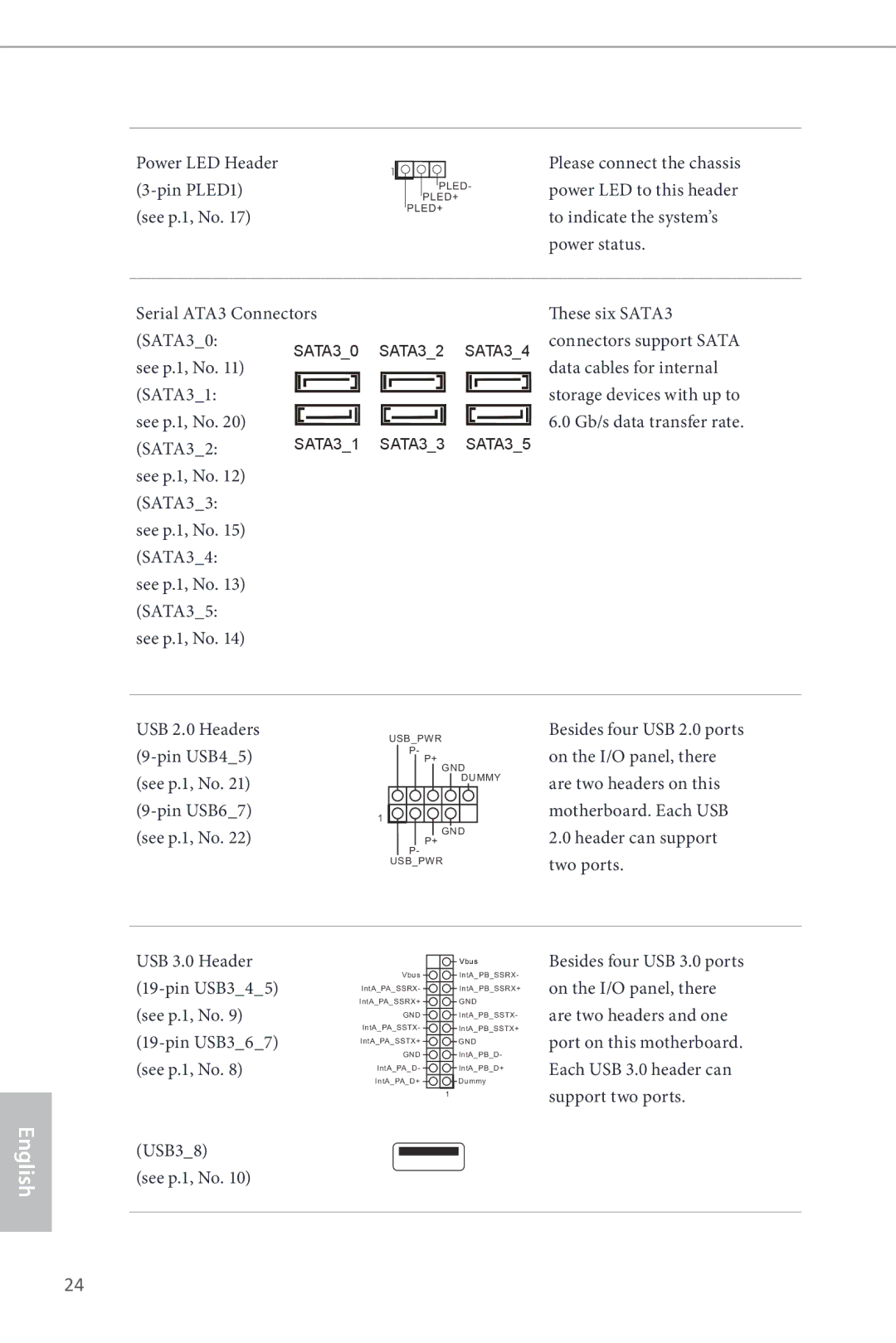
Power status Serial ATA3 Connectors SATA30
Pin PLED1
SATA31 See p.1, No
Chassis Speaker Header
Spdif Out Connector Please connect Pin SPDIFOUT1
Front Panel Audio Header Pin HDAUDIO1 See p.1, No
Pin SPEAKER1 Speaker to this header See p.1, No
Pin IR1
CPU Fan Connectors Pin CPUFAN1 See p.1, No
Wireless transmitting
Receiving infrared module
TPM Header Pin TPMS1 See p.1, No
Einleitung
Lieferumfang
Technische Daten
Rückblende
Support-CD
Anschluss
Funktion
Betriebssystem
CPU/Gehäuselüfter-Mehrfachgeschwindigkeitssteuerung
Spannungsüberwachung +12 V, +5 V, +3,3 V, CPU Vcore
Zertifizierungen
Siehe S , Nr
Jumpereinstellung
Standard Cmos löschen
Integrierte Stiftleisten und Anschlüsse
Systembetriebsstatus mit
Dieser Stiftleiste
Audiostiftleiste
Frontblende
ATX-Netzanschluss Polig, ATXPWR1 Siehe S , Nr
Kennwörter und Daten
System, das Schlüssel
Digitale Zertifikate
Ein TPM-System hilft
Contenu de l’emballage
Spécifications
Du panneau
Réseau
Connectique
Arrière
Tiques du
Stockage
Caractéris
CD inclus
Système
’exploitation Certifications
Voir p.1, No
Configuration des cavaliers jumpers
Cavalier Clear Cmos
Embases et connecteurs de la carte mère
Pwrbtn bouton d’alimentation
SATA31 Voir p.1, No
Système
Connecteurs Serial ATA3
Embase audio du panneau Cette embase sert au Frontal
Embase du haut-parleur
PWRFAN1 à 3 broches voir p.1, No
Embase pour module
Sauvegarder clés, certi
Module de plateforme
Sécurisée, qui permet de
Ficats numériques, mots
Introduzione
Contenuto della confezione
Specifiche
Pannello
Posteriore
Connettore
Che del Bios
Archiviazione
Caratteristi
Certificazioni
ErP/EuP Ready è necessaria alimentazione ErP/EuP ready
Impostazione jumper
Cmos CLRCMOS1
Di collegare i cavi
Header e connettori sulla scheda
Dei pin. Annotare i pin
Header LED di alimentazione PLED1 a 3 pin vedere pag , n
Vedere pag , n Anteriore
Header altoparlante
PWRFAN1 a 3 pin vedere pag , n
Certificati digitali
Password e dati. Un
Modo sicuro chiavi
Sistema TPM permette
Introducción
Contenido del paquete
Especificaciones
Panel trasero
Monitor del hardware
Almace- namiento Conectores
CD de soporte
Certificaciones
FCC, CE, Whql
Predeterminado Borrado de Cmos
Instalación de los puentes
Puente de borrado de
Consulte la pág.1, N.º
Conectores y cabezales incorporados
PLED1 de 3 pines
Cabezal de indicador LED
De alimentación
Del sistema
Consulte la pág.1, N.º Frontal
Cabezal de audio del Este cabezal se utiliza Panel frontal
HDAUDIO1 de 9 pines
ATX
Que puede almacenar
Cabezal TPM Este conector es TPMS1 de 17 pines
Consulte la pág.1, N.º Módulo de Plataforma
De forma segura claves
Введение
Комплект поставки
Спецификация
Аудио
Порты ввода- вывода на задней панели
Ства
Запоминаю
Щие устрой
Разъемы
64-разрядная
Сертификация
Установка перемычек
Колодки и разъемы, расположенные на материнской плате
Pwrbtn кнопка питания
См. стр Данных со скоростью до 6,0 SATA33
SATA34 SATA3 предназначены для
Устройств для передачи
См. стр.1
Аудиопанели
Аудиоколодка передней
Панели Для подключения Контактная, HD
Этой колодке при помощи
Его к контактам
Малошумящего вентилятора
ЦП. Если вы собираетесь
Разъемом питания АТХ
Ключей, цифровых
Способна обеспечить
Надежное хранение
Сертификатов
Introdução
Conteúdo da embalagem
Ranhuras de
Especificações
Memória
Expansão
Traseiro
Áudio
Do painel
Mento
Des do Bios
Armazena
Conector
Bits
Sistema
Operativo
Certificações
CLRCMOS1Predefinição Limpar Cmos Consultar p.1, N.º
Configuração dos jumpers
Jumper para limpar o
Terminais e conectores integrados
Pwrbtn Botão de alimentação
Português
HDAUDIO1 de 9 pinos
Terminal de áudio do
Painel frontal
Consultar p.1, N.º Frontal
Conector de alimentação
Dados. Um sistema TPM
Chaves, certificados
Digitais, palavras-passe e
Também ajuda a melhorar
Giriş
Ambalaj İçeriği
Özellikler
Ses
Arka Panel I/O
Bağlayıcı
Bios Özelliği
Depolama
Destek CDsi
Belgeler
Varsayılan CMOSu Temizle
Bağlantı Teli Kurulumu
CMOSu Temizle Bağlantı Teli
Bkz. sf.1, No
Düzenine göre sıfırlayın
Ekli Bağlantılar ve Bağlayıcılar
Sistem Paneli Bağlantısı
Kabloları bağlarken
SATA31 Bkz. sf.1, No SATA32
Takın
Seri ATA3 Bağlayıcıları SATA30
Bkz. sf.1, No SATA33 SATA34 SATA35
Içindir
CPU Fan Bağlayıcıları 4-pin CPUFAN1 bkz sf.1, No
ATX Güç Bağlayıcısı Pin ATXPWR1 Bkz. sf.1, No
Zamanda ağ güvenliğinin
Sistemini destekler
TPM sistemleri, aynı
Artırılması, dijital
포장 내용물
ATX 폼 팩터
DDR3 Dimm 슬롯 4 개
Wake-On-LAN 지원
VGA 출력 옵션 세 개 D-Sub, DVI-D 및 Hdmi
ALC892 오디오 코덱
PXE 지원
Smbios 2.3.1 지원 CPU, DRAM, PCH 1.05V, PCH 1.5V 전압 다중 조정
IR 헤더 1 개
전압 모니터링 +12V, +5V, +3.3V, CPU Vcore
ErP/EuP 사용 가능ErP/EuP 사용 가능 전원공급장치 필요
점퍼 설정
Clear Cmos 점퍼
온보드 헤더 및 커넥터
PANEL1
SATA34 넥터는 최대 6.0 Gb/s 데
PLED1
이들 6 개의 SATA3 커
페이지, 11 번 항
Spdif 출력 커넥터 Hdmi VGA 카드의 SPDIFOUT1 Spdifout 커넥터를
HDAUDIO1
SPEAKER1
CHAFAN1
있습니다 핀 CPU
PWRFAN1
CPUFAN1 CPU 팬 저소음 팬
CPUFAN2
TPMTrusted Platform
TPM 헤더
17 핀 TPMS1
はじめに
I/O パネルシールド
DDR3 Dimm スロット
I3 / Xeon / Pentium / Celeron に対応
IntelZ87
DDR3 2933+OC/2800OC/2400OC/2133OC
(Realtek ALC892 オーディオコーデック)
つの VGA 出力オプション:D-Sub、DVI-D、HDMI
DVI-D と Hdmi ポートで、HDCP 機能をサポート
ギガビット LAN 10/100/1000 Mb/ 秒
Bios 機能
電圧監視:+12V 、+5V 、+3.3V 、CPU Vcore
ErP/EuP Ready(ErP/EuP ready 電源が必要です)
ジャンパー設定
(p.1、No 参照)
オンボードのヘッダーとコネクター
(p.1 、No 参照)
、No 参照)
(3 ピン PLED1)
(SATA30:
(SATA32:SATA31
(p.1、No 参照) Spdif Out コネクター
(9 ピン HDAUDIO1 )
(4 ピン SPEAKER1)
(2 ピン SPDIFOUT1) Hdmi VGA カードの (p.1、No 参照) Spdifout コネクター
(24 ピン ATXPWR1)
(4 ピン CPUFAN1)
(3 ピン CPUFAN2)
ATX12V 電源コネクター
(17 ピン TPMS1 )
包装清单
Pentium / Celeron
Digi Power (帝捷)设计
ATX 规格尺寸
支持 Intel Turbo Boost 2.0 技术
支持 DVI-D,60Hz 时最大分辨率达
三个 VGA 输出选项:D-Sub、DVI-D 和 Hdmi
支持 Hdmi 技术,60Hz 时最大分辨率达
支持 D-Sub,60Hz 时最大分辨率达
电源 LED 接脚
IR 接脚
COM 端口接脚
TPM 接脚
电压监控:+12V 、+5V 、+3.3V 、CPU Vcore
认证 FCC、CE、WHQL ErP/EuP 支持(需要支持 ErP/EuP 的电源)
跳线设置
板载接脚和接口
USB 2.0 接脚
SATA34 最高 6.0 Gb/s 数据传输
SATA31 Sata 数据线。
USB45 USB 2.0 端口外,此主板
(见第 1 页,第 28 个)
SPDIFOUT1 VGA 卡的 Spdifout
ATX 电源接口
CPU 风扇接口
CPUFAN1
24 针 ATXPWR1
TPM 接脚 此接口支持 Trusted 17 针 TPMS1
電子信息產品污染控制標示
包裝內容
支援 Intel Turbo Boost 2.0 技術
ATX 尺寸
Celeron (LGA1150 封裝)
支援 Intel K-Series unlocked CPU
支援最高達 1920x1200 @ 60Hz 解析度的 DVI-D
三個 VGA 輸出選項:D-Sub、DVI-D 及 Hdmi
支援最高達 1920x1200 @ 60Hz 解析度的 Hdmi 技術
支援最高達 1920x1200 @ 60Hz 解析度的 D-Sub
IR 排針
64Mb AMI Uefi Legal Bios 含多語 GUI 支援
支援 Smbios
COM 連接埠排針
電壓監控:+12V 、+5V 、+3.3V 、CPU Vcore
認證 FCC、CE、WHQL ErP/EuP Ready(需具備 ErP/EuP ready 電源供應器)
跳線設定
板載排針及接頭
SATA33:
11) SATA31
SATA32:
SATA34:
(請參閱第 1 頁,編號 28)
Pin SPDIFOUT1 VGA 卡的 Spdifout
Pin CPU 風扇,請接
Pin PWRFAN1
CPU 風扇接頭
Pin CPUFAN2 Pin 1-3。
149
Pendahuluan
Isi Kemasan
Slot Ekspansi
Spesifikasi
Memori
Grafis
Panel I/O
Belakang
Konektor
Fitur Bios
Penyimpanan
Dukungan CD
Siap untuk ErP/EuP memerlukan catu daya untuk ErP/EuP
64-bit
Sertifikasi
Konfigurasi Jumper
Lihat hal , No
Pwrbtn Switch Daya
Header dan Konektor Onboard
Konektor Serial ATA3 SATA30
Header LED Daya Sambungkan LED daya PLED1 3-pin
Sistem
SATA31 Lihat hal , No SATA32
Lihat hal , No Audio depan
159
Digital, dan memastikan
Keamanan jaringan
Melindungi identitas
Integritas platform
Contact Information