Storage position | Extended position | Thrust on terminal |
Will not get lost. Always ready to use. | Note: Pressure, when handle is | Note: Clamp is released and spring |
| squeezed, holds adapter firm. Will not | tension holds adapter firm. |
| slip back. |
|
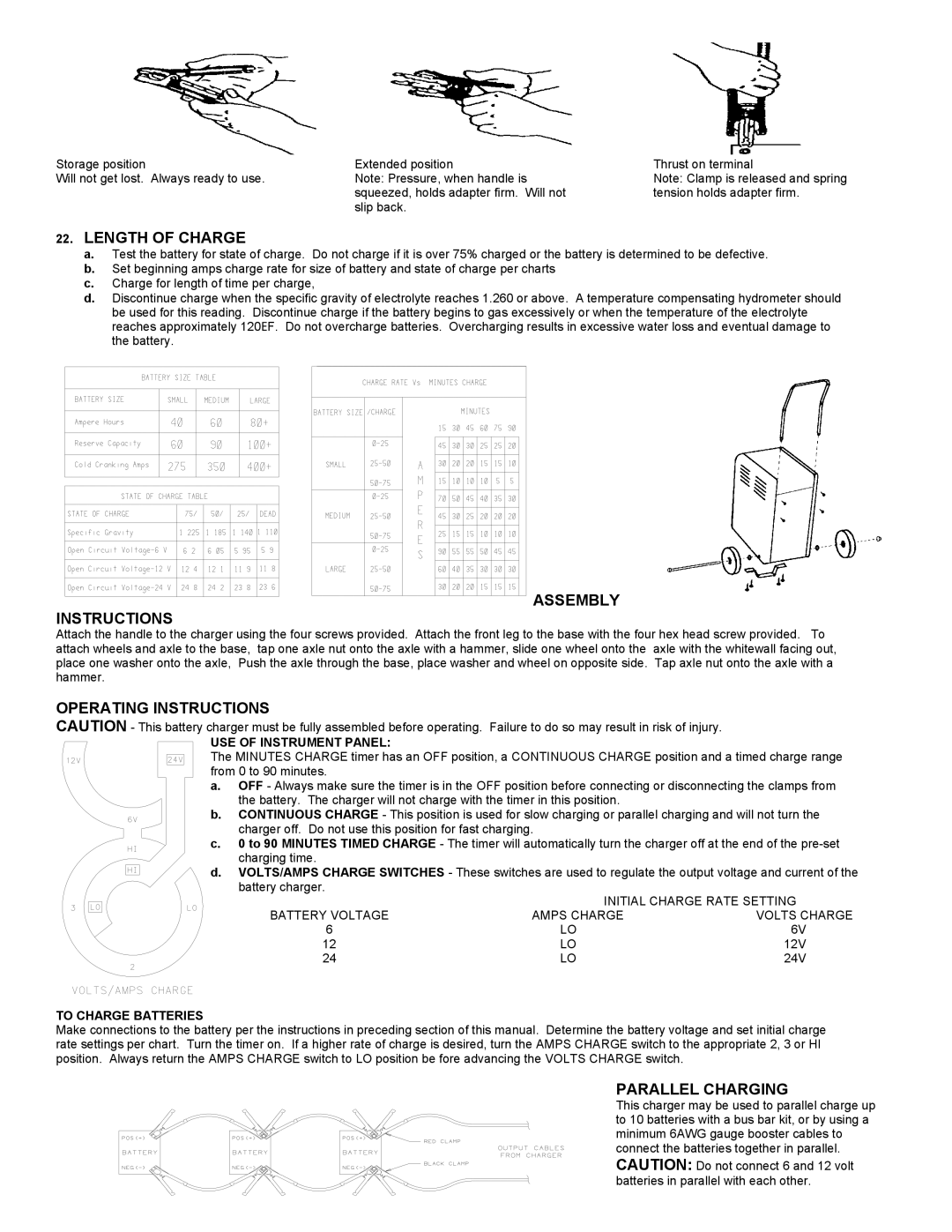
22.LENGTH OF CHARGE
a.Test the battery for state of charge. Do not charge if it is over 75% charged or the battery is determined to be defective.
b.Set beginning amps charge rate for size of battery and state of charge per charts
c.Charge for length of time per charge,
d.Discontinue charge when the specific gravity of electrolyte reaches 1.260 or above. A temperature compensating hydrometer should be used for this reading. Discontinue charge if the battery begins to gas excessively or when the temperature of the electrolyte reaches approximately 120EF. Do not overcharge batteries. Overcharging results in excessive water loss and eventual damage to the battery.
ASSEMBLY
INSTRUCTIONS
Attach the handle to the charger using the four screws provided. Attach the front leg to the base with the four hex head screw provided. To attach wheels and axle to the base, tap one axle nut onto the axle with a hammer, slide one wheel onto the axle with the whitewall facing out, place one washer onto the axle, Push the axle through the base, place washer and wheel on opposite side. Tap axle nut onto the axle with a hammer.
OPERATING INSTRUCTIONS
CAUTION - This battery charger must be fully assembled before operating. Failure to do so may result in risk of injury.
USE OF INSTRUMENT PANEL:
The MINUTES CHARGE timer has an OFF position, a CONTINUOUS CHARGE position and a timed charge range from 0 to 90 minutes.
a.OFF - Always make sure the timer is in the OFF position before connecting or disconnecting the clamps from the battery. The charger will not charge with the timer in this position.
b.CONTINUOUS CHARGE - This position is used for slow charging or parallel charging and will not turn the charger off. Do not use this position for fast charging.
c.0 to 90 MINUTES TIMED CHARGE - The timer will automatically turn the charger off at the end of the
d.VOLTS/AMPS CHARGE SWITCHES - These switches are used to regulate the output voltage and current of the battery charger.
BATTERY VOLTAGE | INITIAL CHARGE RATE SETTING | |
AMPS CHARGE | VOLTS CHARGE | |
6 | LO | 6V |
12 | LO | 12V |
24 | LO | 24V |
TO CHARGE BATTERIES
Make connections to the battery per the instructions in preceding section of this manual. Determine the battery voltage and set initial charge rate settings per chart. Turn the timer on. If a higher rate of charge is desired, turn the AMPS CHARGE switch to the appropriate 2, 3 or HI position. Always return the AMPS CHARGE switch to LO position be fore advancing the VOLTS CHARGE switch.
PARALLEL CHARGING
This charger may be used to parallel charge up to 10 batteries with a bus bar kit, or by using a minimum 6AWG gauge booster cables to connect the batteries together in parallel. CAUTION: Do not connect 6 and 12 volt batteries in parallel with each other.