Page
Page
Chapter 1:
Product introduction
Chapter 2:
BIOS setup
Page
Chapter 3:
Software support
Federal Communications Commission Statement
Canadian Department of Communications Statement
Electrical safety
Operation safety
How this guide is organized
•Chapter 1: Product introduction
•Chapter 2: BIOS setup
•Chapter 3: Software support
Where to find more information
Conventions used in this guide
DANGER/WARNING:
CAUTION:
IMPORTANT
NOTE
CPU
Chipset
System Bus
Memory
Expansion Slots
USB
Back Panel I/O Ports
Internal I/O Connectors
Manageability
BIOS Features
Page
Thank you for buying an ASUS® P5Q SE Plus motherboard
Motherboard
Cables
Accessories
Application DVD
Green ASUS
Core™2 Duo CPU support
Intel® P45 Chipset
PCI Express 2.0 support
FSB 1600 support
ASUS Exclusive features
Express Gate
ASUS Power Saving Solution
ASUS Quiet Thermal Solution
ASUS EZ DIY
ASUS MyLogo2™
AI Booster
Precision Tweaker
C.P.R. (CPU Parameter Recall)
Onboard LED
1.5.1Placement direction
1.5.2Screw holes
1.5.3Motherboard layout
1.10 Connectors
Page
1.6.1Installing the CPU
DO NOT
Page
1.6.2Installing the CPU heatsink and fan
1.6.3Uninstalling the CPU heatsink and fan
1.7.1Overview
Channel
Sockets
1.7.2Memory configurations
P5Q SE Plus Motherboard Qualified Vendors Lists (QVL) DDR2-1066MHz capability
DDR2-800MHz capability
Page
Page
DDR2-667MHz capability
DDR2-667MHz capability
SS - Single-sided /DS - Double - sided
DIMM support:
A*:
C*:
1.7.3Installing a DIMM
1.7.4Removing a DIMM
1.8.1Installing an expansion card
1.8.2Configuring an expansion card
IRQ assignments for this motherboard
1.8.4PCI slots
1.8.5PCI Express x1 slots
1.8.6PCI Express 2.0 x16 slot
1.Clear RTC RAM (3-pinCLRTC)
2.Keyboard power (3-pinKBPWR)
3.USB device wake-up (3-pin USBPW1-5, 3-pin USBPW6-11)
LAN port LED indications
Audio 2, 4, 6, or 8-channelconfiguration
2.IDE connector (40-1pin PRI_EIDE)
Mode of
3.ICH10 Serial ATA connectors (7-pin SATA1-6)
4.Digital audio connector (4-1pin SPDIF_OUT)
5.USB connectors (10-1pin USB78, USB 910, USB1112)
6.Optical drive audio connector (4-pinCD)
CPU, chassis, and power fan connectors
8.Serial port connector (10-1pin COM1)
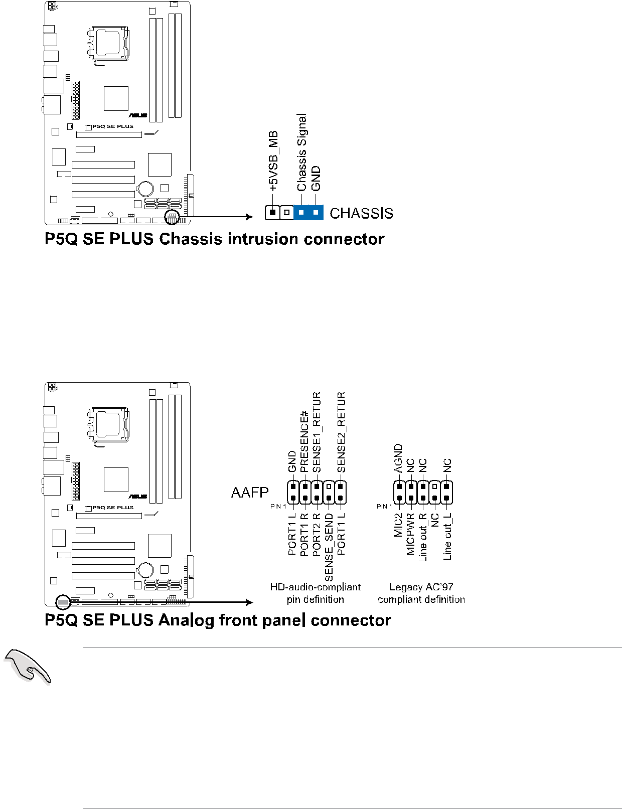
9.Chassis intrusion connector (4-1pin CHASSIS)
10.Front panel audio connector (10-1pin AAFP)
11.ATX power connectors (24-pinEATXPWR, 4-pinATX12V)
12.System panel connector (20-8pin PANEL)
•System power LED (2-pinPLED)
•Hard disk drive activity LED (2-pinIDE_LED)
•System warning speaker (4-pinSPEAKER)
•ATX power button/soft-offbutton (2-pinPWRSW)
ASUS Q-Connector(system panel)
BIOS Beep
1.12.1Using the OS shut down function
1.12.2Using the dual function power switch
2.6 Power Menu
Page
Installing ASUS Update
Updating the BIOS through the Internet
Updating the BIOS through a BIOS file
2.1.2Creating a bootable floppy disk
Start
My Computer
Format
Format 3 1/2 Floppy Disk
2.1.3ASUS EZ Flash 2 utility
EZ Flash2
FAT 32/16
Copying the current BIOS
Updating the BIOS file
Page
Recovering the BIOS from the support DVD
Recovering the BIOS from a USB flash disk
Page
2.2.1BIOS menu screen
2.2.2Menu bar
Main
Ai Tweaker
Advanced
2.2.4Menu items
2.2.5Sub-menuitems
2.2.6Configuration fields
Pop-up
window
2.2.1 BIOS menu screen
2.3.1System Time [xx:xx:xx]
2.3.2System Date [Day xx/xx/xxxx]
2.3.3Legacy Diskette A [1.44M, 3.5 in.]
Type [Auto]
LBA/Large Mode [Auto]
Block (Multi-SectorTransfer) M [Auto]
PIO Mode [Auto]
DMA Mode [Auto]
SMART Monitoring [Auto]
32Bit Data Transfer [Enabled]
SATA Configuration [Enhanced]
Hard Disk Write Protect [Disabled]
AMI BIOS
Processor
System Memory
FSB Frequency [XXX]
PCIE Frequency [Auto]
1st Information:
2nd Information:
3rd Information:
2.4.9Ai Transaction Booster [Auto]
Ai Transaction Booster
2.4.10CPU Voltage [Auto]
2.4.11FSB Termination Voltage [Auto]
2.4.12Memory Voltage [Auto]
2.4.14South Bridge Voltage [Auto]
2.4.15Load-LineCalibration [Auto]
2.4.16CPU GTL Reference [Auto]
2.4.17CPU Spread Spectrum [Auto]
2.4.18PCIE Spread Spectrum [Auto]
CPU Ratio Setting [Auto]
C1E Support [Enabled]
Max CPUID Value Limit [Disabled]
Intel(R) Virtualization Tech [Enabled]
CPU TM Function [Enabled]
Execute-DisableBit Capability [Enabled]
North Bridge Configuration
High Definition Audio [Enabled]
J-MicroneSATA/PATA Controller [Enabled]
Onboard PCIE LAN [Enabled]
Serial Port1 Address [3F8/IRQ4]
USB Functions [Enabled]
USB 2.0 Controller [Enabled]
USB 2.0 Controller Mode [HiSpeed]
BIOS EHCI Hand-off[Enabled]
Legacy USB Support [Auto]
Plug And Play O/S [No]
2.6.1Suspend Mode [Auto]
2.6.2Repost Video on S3 Resume [No]
2.6.3ACPI 2.0 Support [Disabled]
2.6.4ACPI APIC Support [Enabled]
Restore On AC Power Loss [Power Off]
Power On By RTC Alarm [Disabled]
Power On By External Modems [Disabled]
Power On By PCI Devices [Disabled]
Power On By PCIE Devices [Disabled]
Power On By PS/2 Keyboard [Disabled]
Power On By PS/2 Mouse [Disabled]
CPU Temperature [xxxºC/xxxºF]
MB Temperature [xxxºC/xxxºF]
CPU Fan Speed [xxxxRPM] or [Ignored] / [N/A]
CPU Fan Profile [Standard]
Chassis Fan Speed [xxxxRPM] or [Ignored] / [N/A]
Chassis Q-FanControl [Disabled]
Chassis Fan Ratio [Standard]
Power Fan Speed (RPM) [xxxxRPM] or [Ignored] / [N/A]
1st ~ xxth Boot Device [xxx Drive]
Quick Boot [Enabled]
Full Screen Logo [Enabled]
Add On ROM Display Mode [Force BIOS]
Bootup Num-Lock[On]
Wait for ‘F1’ If Error [Enabled]
Change Supervisor Password
User Access Level [Full Access]
Change User Password
Clear User Password
Password Check [Setup]
2.8.1ASUS EZ Flash
Enter OS Timer [10 Seconds]
Reset User Data [No]
Check Realtek LAN cable [Disabled]
Save to Profle 1/2
Load from Profile 1/2
Start O.C. Profile
Exit & Save Changes
Exit & Discard Changes
Discard Changes
Load Setup Defaults
Page
3.2.1Running the support DVD
ASUS InstAll - Installation Wizard for Anti-Virusand Drivers Utility
Norton Internet Security
Intel Chipset Driver Inf Update Program
Realtek RTL8111B/C LAN Drivers
VIA Audio Driver
ASUS InstAll-InstallationWizard for Utilities
ASUS Update
ASUS PC Probe
ASUS AI Suite
Adobe Acrobat Reader
Microsoft DirectX 9.0c
Corel MediaOne Starter
3.2.4Manual menu
3.2.5ASUS Contact information
Motherboard Info
Browse this DVD
Technical support Form