MONITOR PANELS
INSTALLATION INSTRUCTIONS
Atlas Sound Monitor Panels are designed to monitor 25 volt or 70.7 volt speaker lines.
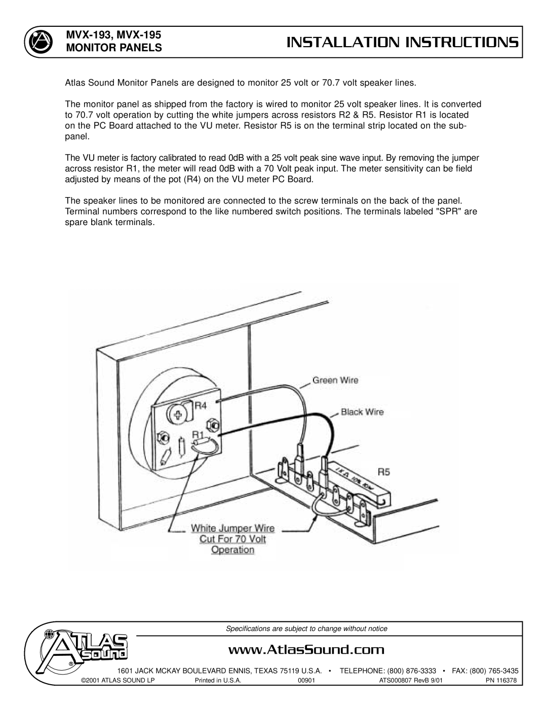
The monitor panel as shipped from the factory is wired to monitor 25 volt speaker lines. It is converted to 70.7 volt operation by cutting the white jumpers across resistors R2 & R5. Resistor R1 is located on the PC Board attached to the VU meter. Resistor R5 is on the terminal strip located on the sub- panel.
The VU meter is factory calibrated to read 0dB with a 25 volt peak sine wave input. By removing the jumper across resistor R1, the meter will read 0dB with a 70 Volt peak input. The meter sensitivity can be field adjusted by means of the pot (R4) on the VU meter PC Board.
The speaker lines to be monitored are connected to the screw terminals on the back of the panel. Terminal numbers correspond to the like numbered switch positions. The terminals labeled "SPR" are spare blank terminals.
Specifications are subject to change without notice
www.AtlasSound.com
1601 JACK MCKAY BOULEVARD ENNIS, TEXAS 75119 U.S.A. • TELEPHONE: (800)
©2001 ATLAS SOUND LP | Printed in U.S.A. | 00901 | ATS000807 RevB 9/01 | PN 116378 |