AT-PROHD48M-R specifications
The Atlona AT-PROHD48M-R is a high-performance 4K HDMI matrix switcher designed for professional audio-visual applications. This versatile device allows users to route multiple HDMI sources to multiple displays, making it a perfect solution for environments like conference rooms, classrooms, and entertainment venues.One of the standout features of the AT-PROHD48M-R is its ability to support a variety of resolutions, including 4K at 60Hz with 4:4:4 chroma subsampling, ensuring high-quality video output. This capability is crucial for modern multimedia applications where high-definition video is a necessity. The switcher also supports HDMI 2.0 and HDCP 2.2, making it compatible with the latest content protection technologies.
The AT-PROHD48M-R includes advanced audio management features, such as embedded audio extraction, allowing users to separate audio from the HDMI signal for external processing. Its comprehensive audio support covers a range of formats, including multi-channel audio, ensuring flexibility for diverse audio setups.
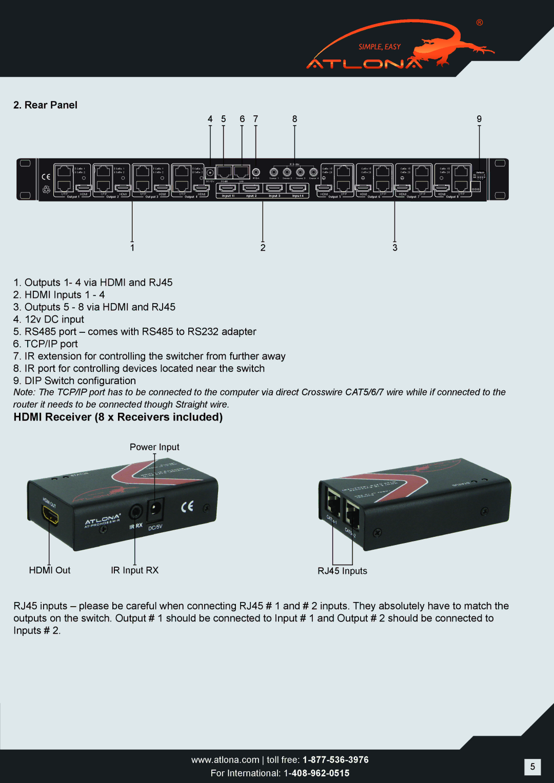
In terms of connectivity, the switcher features 48 HDMI inputs and 8 HDMI outputs, providing ample connectivity for multiple devices. This extensive input/output configuration is essential for environments with numerous source devices and display screens. The matrix switcher can also be controlled via RS-232, IR, and IP, making it user-friendly and easy to integrate into existing systems.
A critical technology within the AT-PROHD48M-R is its built-in EDID management, which helps to ensure that all connected devices can communicate effectively, thus optimizing video performance. The switcher also incorporates a user-friendly on-screen display (OSD) for easy navigation and setup, simplifying the user experience.
The robust construction of the AT-PROHD48M-R ensures durability and reliability, key factors in professional environments. It is designed to support long cable runs, making it a flexible option for larger installations.
In summary, the Atlona AT-PROHD48M-R is an advanced HDMI matrix switcher that combines high-quality video performance, extensive connectivity options, and user-friendly control features. It stands as a reliable choice for any professional audiovisual installation that demands superior matrix switching capabilities, making it an essential tool for optimizing media presentations.

