¨
3
Quasar 12-Volt 2-Mile Navigational Light
Without Wire Leads:
With 7" Wire Leads:
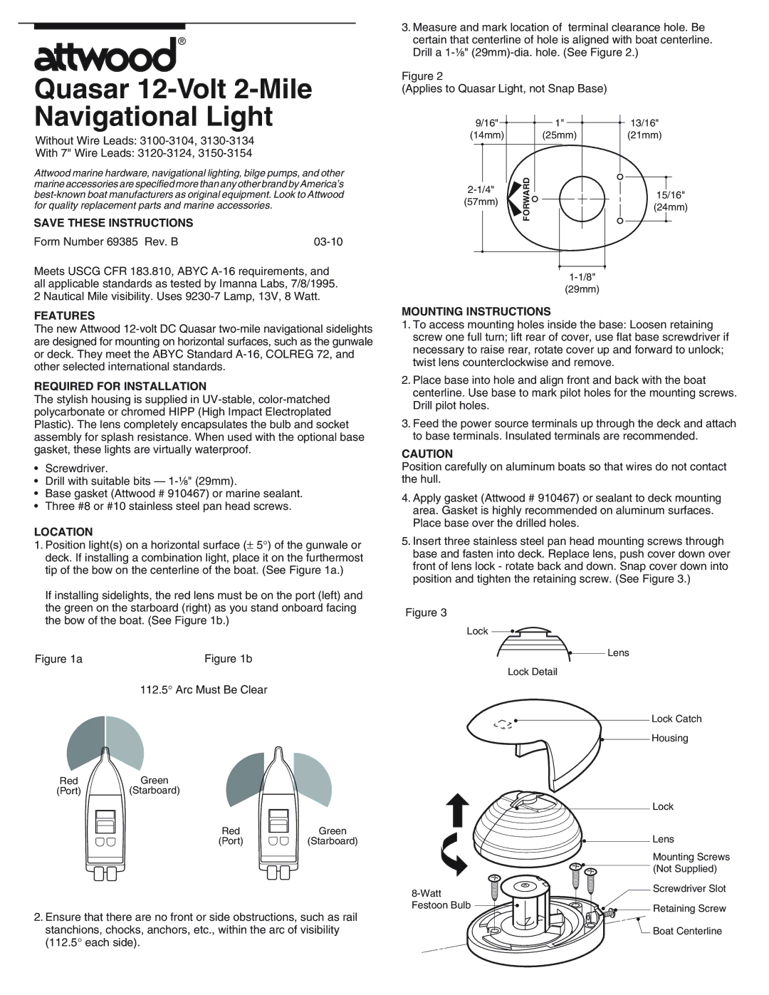
3.Measure and mark location of terminal clearance hole. Be certain that centerline of hole is aligned with boat centerline. Drill a
Figure 2
(Applies to Quasar Light, not Snap Base)
9/16" | ¥ | ¥ |
| 1" | ¥ | ¥ | 13/16" |
(14mm) |
| (25mm) |
| (21mm) | |||
¥ |
|
|
|
|
|
|
|
Attwood marine hardware, navigational lighting, bilge pumps, and other marine accessories are specified more than any other brand by AmericaÕs
SAVE THESE INSTRUCTIONS
Form Number 69385 Rev. B |
Meets USCG CFR 183.810, ABYC
(57mm)
¥
![]() FORWARD
FORWARD
¥
¥
15/16"
(24mm)
¥
¥
all applicable standards as tested by Imanna Labs, 7/8/1995. 2 Nautical Mile visibility. Uses
FEATURES
The new Attwood
REQUIRED FOR INSTALLATION
The stylish housing is supplied in
¥Screwdriver.
¥Drill with suitable bits Ñ
¥Base gasket (Attwood # 910467) or marine sealant.
¥Three #8 or #10 stainless steel pan head screws.
LOCATION
1.Position light(s) on a horizontal surface (± 5°) of the gunwale or deck. If installing a combination light, place it on the furthermost tip of the bow on the centerline of the boat. (See Figure 1a.)
If installing sidelights, the red lens must be on the port (left) and the green on the starboard (right) as you stand onboard facing the bow of the boat. (See Figure 1b.)
Figure 1a | Figure 1b |
112.5° Arc Must Be Clear
Red | Green |
(Port) | (Starboard) |
Red | Green |
(Port) | (Starboard) |
2.Ensure that there are no front or side obstructions, such as rail
stanchions, chocks, anchors, etc., within the arc of visibility (112.5° each side).
(29mm)
MOUNTING INSTRUCTIONS
1.To access mounting holes inside the base: Loosen retaining screw one full turn; lift rear of cover, use flat base screwdriver if necessary to raise rear, rotate cover up and forward to unlock; twist lens counterclockwise and remove.
2.Place base into hole and align front and back with the boat centerline. Use base to mark pilot holes for the mounting screws. Drill pilot holes.
3.Feed the power source terminals up through the deck and attach to base terminals. Insulated terminals are recommended.
CAUTION
Position carefully on aluminum boats so that wires do not contact the hull.
4.Apply gasket (Attwood # 910467) or sealant to deck mounting area. Gasket is highly recommended on aluminum surfaces. Place base over the drilled holes.
5.Insert three stainless steel pan head mounting screws through base and fasten into deck. Replace lens, push cover down over front of lens lock - rotate back and down. Snap cover down into position and tighten the retaining screw. (See Figure 3.)
Figure 3
Lock •
• | Lens |
Lock Detail |
|
• | Lock Catch |
• | Housing |
| • |
| Lock |
|
| • | Lens |
|
| • | Mounting Screws |
|
| (Not Supplied) | |
|
| Screwdriver Slot | |
• |
|
| |
Festoon Bulb | • • | Retaining Screw | |
| |||
|
|
| • |
|
|
| Boat Centerline |