LED Mini Courtesy Light
6316, 6317, 6318 and 6319
SAVE THESE INSTRUCTIONS |
|
Form Number 69436 Rev. A |
![]() WARNING
WARNING
Remove vessel from water before using any
REQUIRED FOR INSTALLATION
•3/4" (19mm) diameter hole saw or drill bit
•
•
•
•
MOUNTING LOCATION
•Mount to any flat surface – minimum clearance of 7/8" (22mm) required behind mounting surface (measured from face of mounting surface). (Figure 1)
•Be sure there are no fuel, water or electric lines behind surface where you will be drilling.
CUT-OUT INSTRUCTIONS
1.At selected mounting location, carefully mark center of hole.
2.Use 3/4" (19mm) diameter hole saw or drill bit to cut hole.
MOUNTING INSTRUCTIONS
1.Add rubber grommet to light (Figure 2).
2.Connect wire to power source (see FINAL WIRING INSTRUCTIONS).
3.Snap light into hole.
FINAL WIRING INSTRUCTIONS
Connect to
Use
1.Connect positive pole of 12VDC battery to red wire,
2.Connect white wire from light to switch.
3.Connect black (negative) wire to negative pole of battery.
4.Neatly thread wires, avoiding areas where abrasion or snagging may occur.
ATTWOOD LIMITED 10-YEAR WARRANTY
This Attwood product carries a limited ten (10) year warranty. This is a
Figure 1 / Figura 1 |
|
|
|
|
| A |
|
| |||||
Abbildung 1 / Figur 1 |
|
|
| |||
|
|
|
| |||
|
|
|
|
|
|
|
B
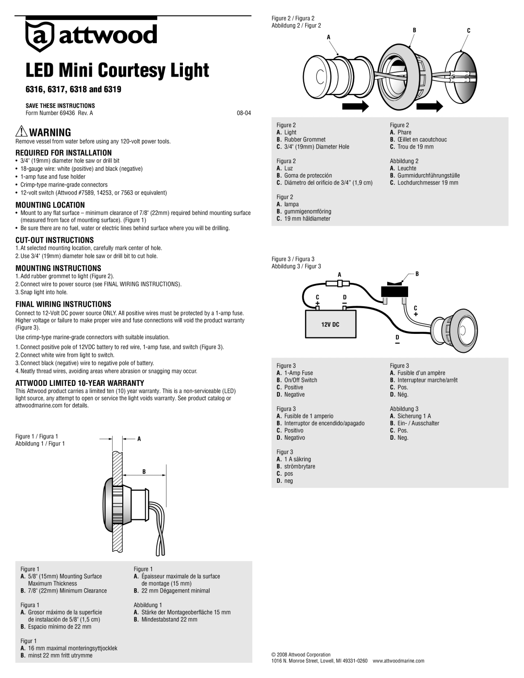
Figure 2 / Figura 2
Abbildung 2 / Figur 2
BC
A
Figure 2 | Figure 2 |
A. Light | A. Phare |
B. Rubber Grommet | B. Œillet en caoutchouc |
C. 3/4" (19mm) Diameter Hole | C. Trou de 19 mm |
Figura 2 | Abbildung 2 |
A. Luz | A. Leuchte |
B. Goma de protección | B. Gummidurchführungstülle |
C. Diámetro del orificio de 3/4” (1,9 cm) | C. Lochdurchmesser 19 mm |
Figur 2
A.lampa
B.gummigenomföring
C.19 mm håldiameter
Figure 3 / Figura 3
Abbildung 3 / Figur 3
A | B |
C | D |
|
|
| C |
12V DC |
|
|
|
| D |
Figure 3 |
| Figure 3 |
A. |
| A. Fusible d’un ampère |
B. On/Off Switch |
| B. Interrupteur marche/arrêt |
C. Positive |
| C. Pos. |
D. Negative |
| D. Nég. |
Figura 3 |
| Abbildung 3 |
A. Fusible de 1 amperio |
| A. Sicherung 1 A |
B. Interruptor de encendido/apagado | B. | |
C. Positivo |
| C. Pos. |
D. Negativo |
| D. Neg. |
Figur 3
A.1 A säkring
B.strömbrytare
C.pos
D.neg
Figure 1
A.5/8" (15mm) Mounting Surface Maximum Thickness
B.7/8" (22mm) Minimum Clearance
Figura 1
A.Grosor máximo de la superficie de instalación de 5/8" (1,5 cm)
B.Espacio mínimo de 22 mm
Figur 1
A.16 mm maximal monteringsyttjocklek
B.minst 22 mm fritt utrymme
Figure 1
A.Épaisseur maximale de la surface de montage (15 mm)
B.22 mm Dégagement minimal
Abbildung 1
A.Stärke der Montageoberfläche 15 mm
B.Mindestabstand 22 mm
© 2008 Attwood Corporation
1016 N. Monroe Street, Lowell, MI