®
3
4" and 6" Flush Mounted Cleat
66510, 66511, 66512, 66513, 66514, 66516
Installation Instructions
SAVE THESE INSTRUCTIONS
Form Number 69343 Rev. G |
APPLICATION
Attwood flush
REQUIRED FOR INSTALLATION |
|
| |
• Adjustable wrench | • Sabre saw | ||
• | Length of 3/8" (9.5mm) I.D. hose | • | Screwdriver |
• | Cordless drill and bits | • | Marine sealant |
FLUSH CLEAT INSTALLATION INSTRUCTIONS
NOTE: Before you drill or cut a hole on your boat, BE ABSOLUTELY CERTAIN there is room for the unit beneath the deck or gunwale where it will be installed. The cleat mechanism, in the down position, will be recessed beneath the deck or gunwale.
1.Use templates provided to mark opening in deck (Figure 1 or 2). Cut using sabre saw and drill four 1/4" (6.4mm) holes where indicated
2.Remove the supplied fasteners from the studded cleat. Apply a small bead of marine sealant around the edge of the
3.Align backing plate with the underside of the cleat. For the 4"
4.Ensure the screw is long enough to provide for proper engagement with the nut. Attach washers and nuts to the studs or screws and tighten.
![]() WARNING:
WARNING:
The Flush Cleats are not to be used for towing, lifting, or for any other anchoring application beyond those listed above. Any misuse of the intended application may result in personal injury and/or damage to the boat.
OPTIONAL WATER RECEPTACLE INSTALLATION. (Water receptacle sold separately.)
If using the water receptacle on:
The same
1.Place water receptacle on underside of cleat and attach per flush cleat installation instructions (Figure 3). The screws used must be long enough to go through the flange of the cleat, deck, mounting plate and then the water receptacle.
2.Connect 3/8" inner diameter hose to the fitting on the receptacle. Route the hose into the bilge or to a drain fitting.
Figure 3 | • | Machine Screws |
• |
Tension/Travel
![]()
![]()
![]() •Adjustment
•Adjustment
Set Screw
• | |
• | Marine Sealant |
Studded Version
1.After the cleat has been installed, attach water receptacle to the backing plate using (4) #8
2.Connect 3/8" inner diameter hose to the fitting on the water receptacle. Route hose into bilge or to a drain fitting.
Figure 4 | • | Studded Flush Cleat |
|
![]() •Studs
•Studs
• | |
• | Marine Sealant |
• | Backing Plate |
• | Lock Washer |
![]() WARNING:
WARNING:
To prevent personal injury, always disconnect the power source when installing or servicing this product. Always remove the boat from the water before using any 120V AC power tools.
LOCATION
Select an installation location that meets the following criteria:
•Location on vessel must be able to withstand loads specified in application section. See ABYC Reg.
•Location is large enough and wide enough to accommodate the entire cleat body.
•Access to the underside of the vessel is necessary for both models in order to tighten the fasteners.
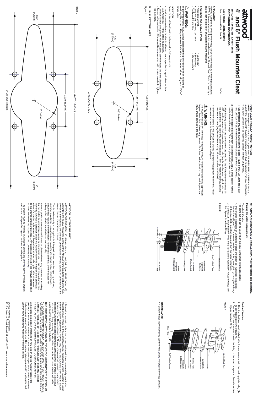
FLUSH CLEAT TEMPLATES
• | Backing Plate |
•Water
Receptacle
(Sold Separately)
| • |
|
Hose Fitting | • | Lock Washer |
• | Nut |
|
| • |
| Nut |
|
|
| • | Water |
|
|
| Receptacle | |
|
|
|
| |
|
|
|
| (Sold Separately) |
Hose Fitting | • | • |
| |
|
|
|
|
MAINTENANCE
• A silicone based lubricant maybe used on cleat shafts to increase the ease of travel.
Figure 1
4.764" (12.1cm)
![]() 1.657" (4.21cm)
1.657" (4.21cm) ![]()
|
|
|
|
|
| 7/8" Radius |
|
| ||||
|
|
|
|
|
|
|
| |||||
1.429" |
|
|
|
|
|
| 1.75" |
| ||||
(3.63cm) |
|
|
|
|
|
|
| (4.45cm) | ||||
|
|
|
|
|
|
|
|
|
|
|
|
|
|
|
|
|
|
|
|
|
|
|
|
|
|
|
|
|
|
|
|
|
|
|
|
|
|
|
|
|
|
|
|
|
|
|
|
|
|
|
|
|
|
|
|
|
|
|
|
|
|
|
|
|
4"
Figure 2
6.475" (16.45cm)
2.220" (5.64cm)
| 1" Radius |
1.650" | 2" |
(4.19cm) | (5.08cm) |
ATTWOOD LIMITED WARRANTY
ATTWOOD CORPORATION, 1016 North Monroe, Lowell, Michigan 49331 (“Attwood”) warrants to the original consumer purchaser that Attwood brand products will be free from defects in materials and workmanship under normal use and service for one year from the date of original consumer purchases.
This limited warranty is not applicable if the product has been damaged by accident, improper installation, unreasonable or improper use, lack of proper maintenance, unauthorized repairs or modifications, normal wear and tear, or other causes not arising out of defects in materials or workmanship.
Attwood products are warranted for use on pleasure boats. Any other use — including but not limited to commercial, racing, or
to the original consumer purchaser. Any expenses involved in the removal, reinstallation or transportation of the product are not covered by this warranty.
The product must be returned to Attwood’s plant at the address above, postage prepaid, and insured with proof of original purchase including date.
If Attwood is unable to replace the product and repair is not commercially practical or cannot be timely made, or if the original consumer purchaser is willing to accept a refund in lieu of repair or replacement, Attwood may refund the purchase price, less an amount for depreciation. The acceptance by Attwood of any product returned or any refund provided by Attwood shall not be deemed an admission that the product is defective
or in violation of any warranty. Products that are replaced or for which a refund is issued become the property of Attwood.
THIS WARRANTY IS ATTWOOD’S ONLY EXPRESS WARRANTY OF THIS PRODUCT. NO IMPLIED WARRANTY SHALL EXTEND BEYOND ONE (1) YEAR FROM THE DATE OF ORIGINAL CONSUMER PURCHASE. ATTWOOD SHALL NOT BE LIABLE FOR ANY DAMAGES FOR LOSS OF USE OF THIS PRODUCT, NOR FOR ANY OTHER INCIDENTAL OR CONSEQUENTIAL DAMAGES, COSTS OR EXPENSES.
Some states do not allow limitations on how long an implied warranty lasts or the exclusion or limitation of incidental or consequential damages, so the above limitations and exclusions may not apply to you. This warranty gives you specific legal rights, and you may have other rights which vary from state to state.
6" | © 2003 Attwood Corporation |
1016 N. Monroe Street, Lowell, MI |