PB1 30-024T
Installation Instructions
2 4 V Lo w Vo l tag e P o we r B as e
 Introduction
The
Although the
 Installation Guidelines
Cut power to the heating system at the main power panel to avoid electrical shock. Installation should be carried out by an electrician.
For a new installation, choose a location about 5 ft. (1.5 m) above the floor.
The thermostat should be installed facing the heating system and on an inside wall.
Avoid locations where there are air drafts (top of staircase, air outlet), dead air spots (behind a door), direct sunlight or con- cealed chimneys or stove pipes.
Included Parts
n One (1)
pTwo (2) mounting screws
 Installation Steps
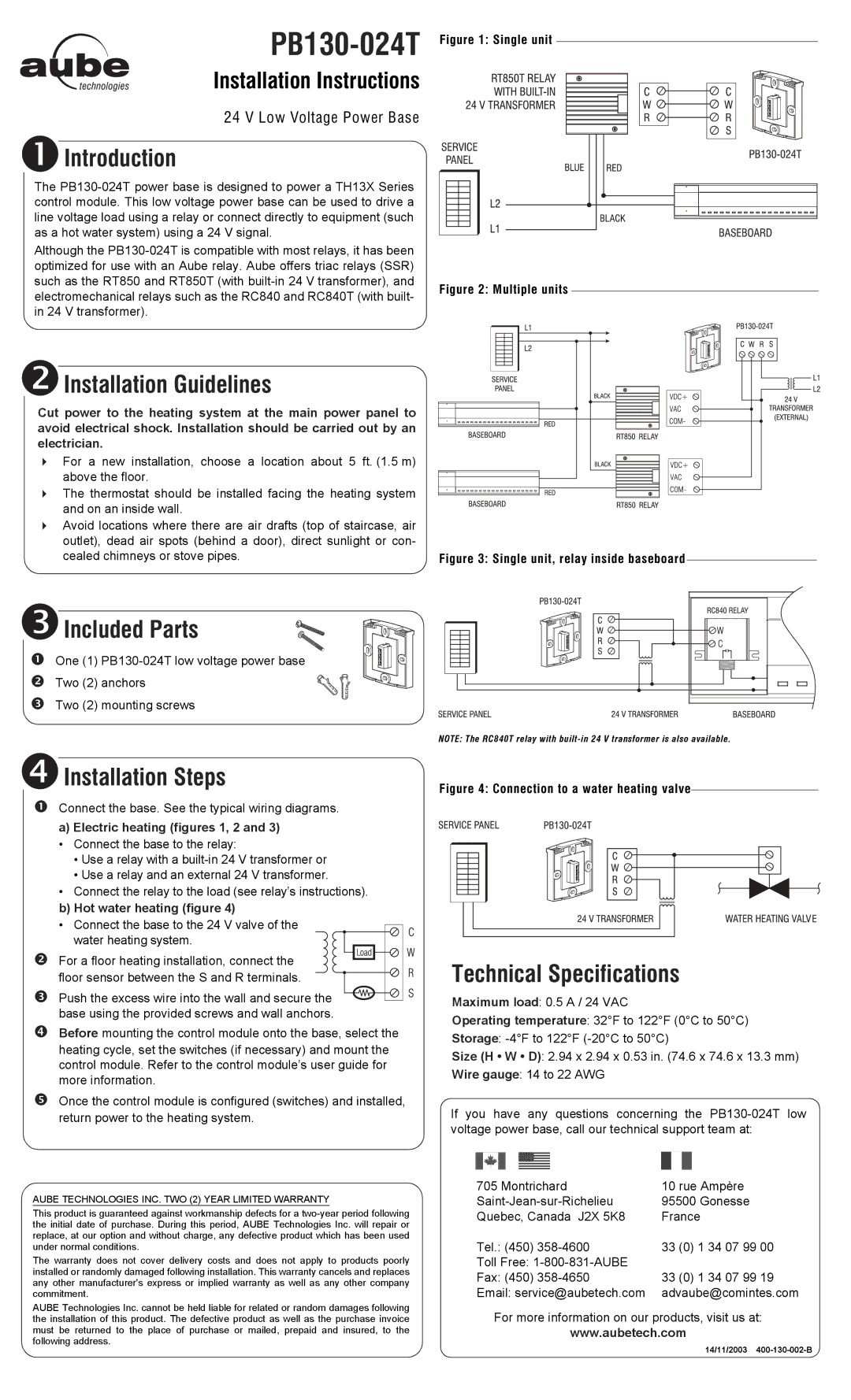
nConnect the base. See the typical wiring diagrams.
a)Electric heating (figures 1, 2 and 3)
• Connect the base to the relay:
•Use a relay with a
•Use a relay and an external 24 V transformer.
•Connect the relay to the load (see relay’s instructions). b) Hot water heating (figure 4)
•Connect the base to the 24 V valve of the water heating system.
o For a floor heating installation, connect the floor sensor between the S and R terminals.
p Push the excess wire into the wall and secure the base using the provided screws and wall anchors.
qBefore mounting the control module onto the base, select the heating cycle, set the switches (if necessary) and mount the control module. Refer to the control module’s user guide for more information.
rOnce the control module is configured (switches) and installed, return power to the heating system.
AUBE TECHNOLOGIES INC. TWO (2) YEAR LIMITED WARRANTY
This product is guaranteed against workmanship defects for a
The warranty does not cover delivery costs and does not apply to products poorly installed or randomly damaged following installation. This warranty cancels and replaces any other manufacturer's express or implied warranty as well as any other company commitment.
AUBE Technologies Inc. cannot be held liable for related or random damages following the installation of this product. The defective product as well as the purchase invoice must be returned to the place of purchase or mailed, prepaid and insured, to the following address.
Technical Specifications
Maximum load: 0.5 A / 24 VAC
Operating temperature: 32°F to 122°F (0°C to 50°C)
Storage:
Size (H • W • D): 2.94 x 2.94 x 0.53 in. (74.6 x 74.6 x 13.3 mm)
Wire gauge: 14 to 22 AWG
If you have any questions concerning the
705 Montrichard | 10 rue Ampère |
95500 Gonesse | |
Quebec, Canada J2X 5K8 | France |
Tel.: (450) | 33 (0) 1 34 07 99 00 |
Toll Free: |
|
Fax: (450) | 33 (0) 1 34 07 99 19 |
Email: service@aubetech.com | advaube@comintes.com |
For more information on our products, visit us at:
www.aubetech.com
14/11/2003
