
AC5C specifications
The AudioSource AC5C is a remarkable piece of audio equipment engineered to elevate your audio experience, whether for home theater applications or general music enjoyment. It boasts a sleek and modern design that seamlessly fits into a variety of settings, making it a versatile choice for any listener.One of the standout features of the AC5C is its robust construction which ensures durability while maintaining acoustic integrity. The speaker is crafted with high-quality materials that minimize distortion, allowing for a clear and accurate sound reproduction. The AC5C is designed to deliver exceptional clarity in vocals and enhances the overall frequency response, making it suitable for dialogue in movies as well as music playback.
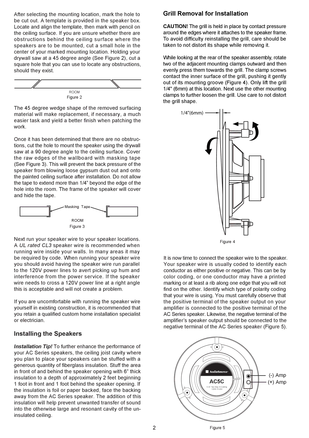
In terms of technology, the AudioSource AC5C incorporates advanced driver components. The speaker unit is equipped with a 5.25-inch woofer and a 1-inch silk dome tweeter. This combination allows for a balanced sound signature where lows, mids, and highs coexist harmoniously. The woofer's design provides strong bass performance without muddiness, while the silk dome tweeter delivers smooth high frequencies that do not fatigue the ears.
The AC5C offers flexible connectivity options, including both wired and wireless capabilities, making integration into various systems easy. The speaker is compatible with a range of audio sources, from traditional amplifiers to modern Bluetooth-enabled devices. This versatility ensures that users can enjoy their favorite content with minimal hassle.
Another notable characteristic of the AudioSource AC5C is its adaptability in installation. It can function as a standalone speaker or be seamlessly integrated into a larger surround sound system. Its form factor is compact, allowing for both wall-mounting and bookshelf placement.
Additionally, the AC5C features impedance-friendly specifications that make it compatible with a wide array of amplifiers. Its efficiency rating means that it can produce substantial sound output even with lower power inputs, catering to both audiophiles and everyday users.
In conclusion, the AudioSource AC5C represents a perfect blend of innovative technology, quality construction, and user-friendly features. With its impressive sound performance and versatile design, it stands as a compelling option for anyone serious about their audio experience. Whether you are an enthusiast looking to enhance your sound system or a casual listener wanting better audio quality, the AC5C is sure to impress.