E. Controls, Indicators, and Connectors
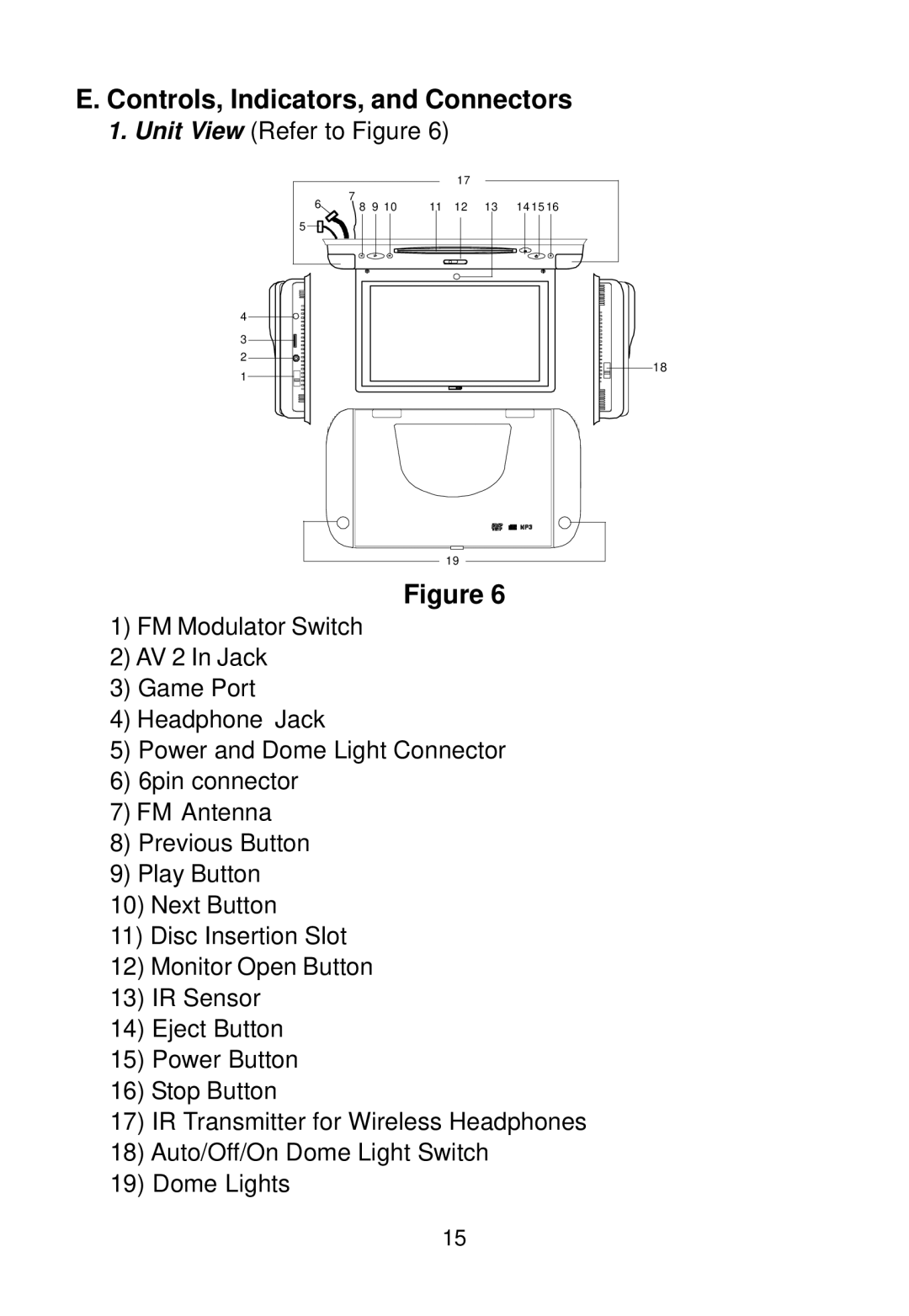
1.Unit View (Refer to Figure 6)
|
|
|
| 17 |
|
|
6 | 7 |
|
|
|
|
|
8 | 9 10 | 11 | 12 | 13 | 14 15 16 | |
5 |
|
|
|
|
|
|
4
3
2
1
19 |
Figure 6
1)FM Modulator Switch
2)AV 2 In Jack
3)Game Port
4)Headphone Jack
5)Power and Dome Light Connector
6)6pin connector
7)FM Antenna
8)Previous Button
9)Play Button
10)Next Button
11)Disc Insertion Slot
12)Monitor Open Button
13)IR Sensor
14)Eject Button
15)Power Button
16)Stop Button
17)IR Transmitter for Wireless Headphones
18)Auto/Off/On Dome Light Switch
19)Dome Lights
18
15
