F. Controls, Indicators, and Connectors
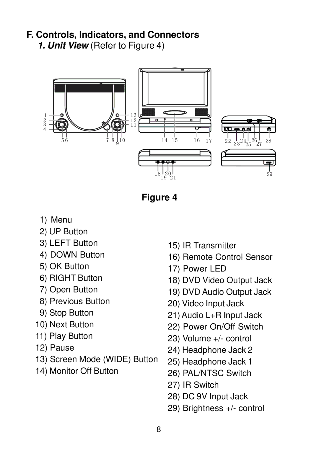
1.Unit View (Refer to Figure 4)
Figure 4
1)Menu
2)UP Button
3) | LEFT Button | 15) | IR Transmitter |
4) | DOWN Button | 16) | Remote Control Sensor |
5) | OK Button | 17) | Power LED |
6) RIGHT Button | 18) DVD Video Output Jack | ||
7) | Open Button | 19) DVD Audio Output Jack | |
8) | Previous Button | 20) Video Input Jack | |
9) | Stop Button | 21) Audio L+R Input Jack | |
10) Next Button | 22) | Power On/Off Switch | |
11) | Play Button | 23) Volume +/- control | |
12) Pause | 24) Headphone Jack 2 | ||
13) Screen Mode (WIDE) Button | 25) Headphone Jack 1 | ||
14) Monitor Off Button | 26) | PAL/NTSC Switch | |
|
| 27) | IR Switch |
|
| 28) DC 9V Input Jack | |
|
| 29) | Brightness +/- control |
8