Power Supply Hookup
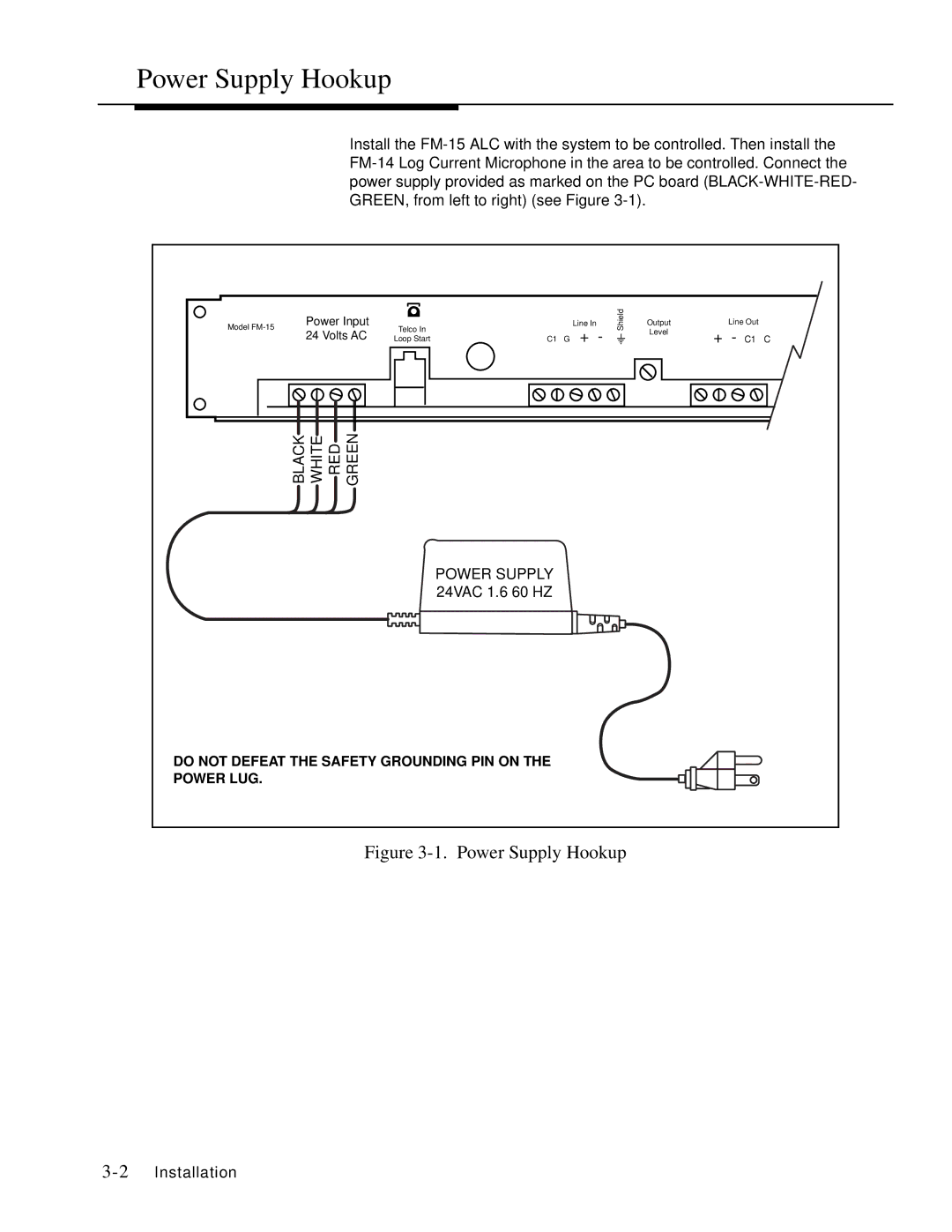
Install the
Model | Power Input | Telco In |
|
| Line In | Shield | Output |
| Line Out |
|
|
|
|
|
| ||||||
| 24 Volts AC | Loop Start | C1 | G | + | - | Level | + | - C1 | C |
|
| |||||||||
| BLACK WHITE RED GREEN |
|
|
|
|
|
|
|
|
|
|
|
| POWER SUPPLY |
|
|
|
|
|
|
|
|
|
| 24VAC 1.6 60 HZ |
|
|
|
|
|
|
|
DO NOT DEFEAT THE SAFETY GROUNDING PIN ON THE |
|
|
|
|
|
|
| |||
POWER LUG. |
|
|
|
|
|
|
|
|
|
|