AXIS P1425–LE Network Camera
Technical Specifications
Function/group | Item | Specifications |
|
|
|
| Video | AXIS Camera Companion (software included on CD) — Basic surveillance for small |
| management | businesses, where video is recorded to edge storage. |
| software | AXIS Camera Station (sold separately) — Fully featured surveillance for |
|
| installations, where video is recorded on a system server. |
|
| For more information and software applications from partners, see |
|
| www.axis.com/products/video/software/ |
|
|
|
| Optional | AXIS T94F01M |
| accessories | AXIS T91A47 Pole Mount (requires AXIS T94F01S Mounting Bracket) |
|
| AXIS T94P01B Corner Bracket (requires AXIS T94F01M |
|
| AXIS T94F01P Conduit Back Box |
|
| Axis PoE Midspans |
|
|
|
Connectors
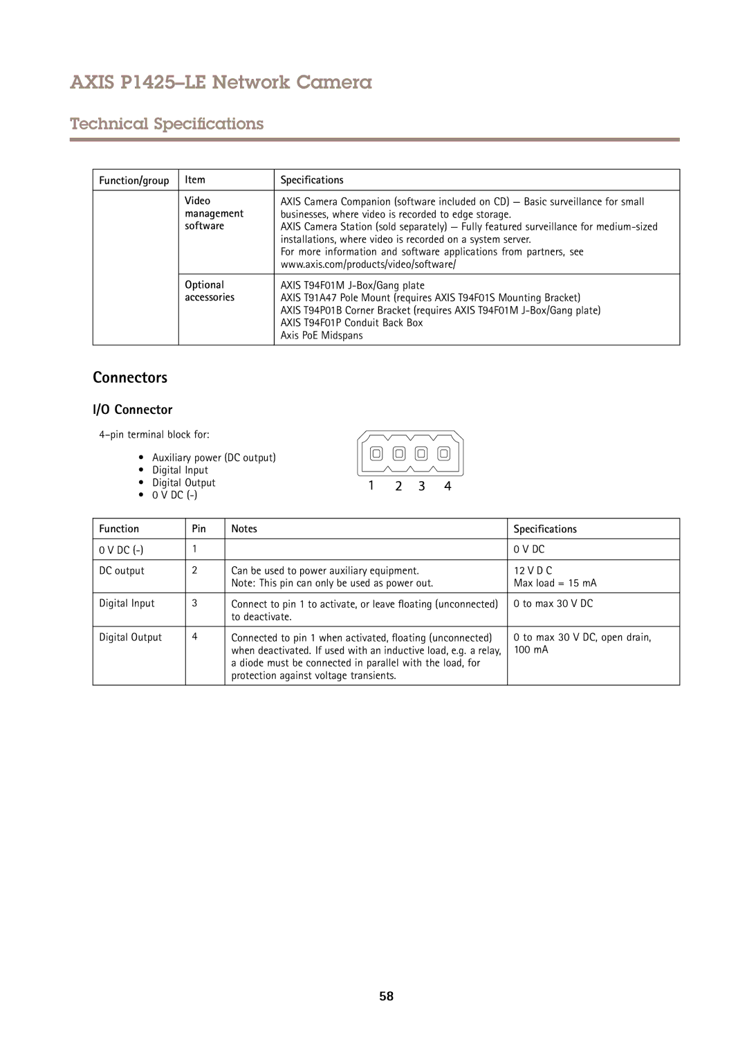
I/O Connector
• Auxiliary power (DC output)
• Digital Input
• Digital Output
• 0 V DC
Function | Pin | Notes | Specifications |
|
|
|
|
0 V DC | 1 |
| 0 V DC |
|
|
|
|
DC output | 2 | Can be used to power auxiliary equipment. | 12 V D C |
|
| Note: This pin can only be used as power out. | Max load = 15 mA |
|
|
|
|
Digital Input | 3 | Connect to pin 1 to activate, or leave floating (unconnected) | 0 to max 30 V DC |
|
| to deactivate. |
|
|
|
|
|
Digital Output | 4 | Connected to pin 1 when activated, floating (unconnected) | 0 to max 30 V DC, open drain, |
|
| when deactivated. If used with an inductive load, e.g. a relay, | 100 mA |
|
| a diode must be connected in parallel with the load, for |
|
|
| protection against voltage transients. |
|
|
|
|
|
58