IS40, IS40P specifications
The BEA IS40P and IS40 are advanced infrared safety sensors designed for a variety of applications, particularly in the realm of automatic doors and industrial automation. These sensors exemplify cutting-edge technology and excellent functionality, making them reliable solutions for ensuring safety in both commercial and industrial environments.One of the standout features of the BEA IS40P and IS40 is their precision in detecting moving objects. They utilize proprietary infrared technology that allows them to sense human presence accurately, enabling them to prevent accidents in high-traffic areas. The sensors have a wide detection range, which is adjustable according to specific needs, ensuring optimal performance in various settings.
The IS40 series is equipped with advanced anti-collision and anti-intrusion features, making them highly effective in detecting potential hazards. This capability significantly enhances workplace safety, especially in environments where machinery operates near personnel. Their seamless integration with automatic doors allows for instant opening and closing, maximizing operational efficiency while maintaining safety.
Another key characteristic of the IS40P and IS40 sensors is their robust construction. Designed to withstand harsh environmental conditions, these sensors are built with durable materials that resist impact and corrosion. This resilience ensures a long operational life, reducing maintenance costs and enhancing overall reliability.
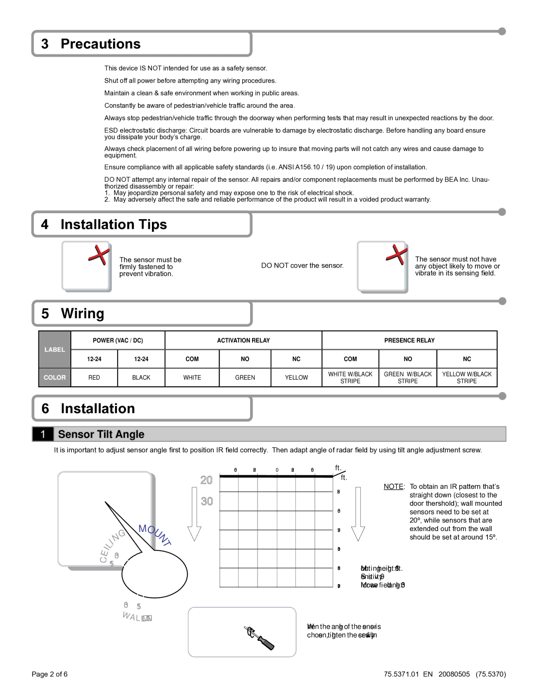
Additionally, the IS40P and IS40 sensors support various installation configurations, including wall mounting and surface mounting. The flexibility in installation options allows for easy integration into existing systems, making them an ideal choice for retrofitting projects. Their sleek and unobtrusive design ensures they blend well with modern architectural styles.
Both the IS40P and IS40 incorporate advanced LED indicators that provide real-time feedback on sensor status and operation. This feature simplifies troubleshooting and maintenance, making it easier for technicians to identify issues promptly. Moreover, these sensors are designed to be energy-efficient, contributing to lower operational costs.
In summary, the BEA IS40P and IS40 infrared safety sensors represent a significant advancement in safety technology. Their combination of precise detection capabilities, robust construction, installation flexibility, and user-friendly features make them an invaluable asset in ensuring safety and efficiency in any environment where automatic doors or machinery are in use. With the IS40 series, BEA continues to set a high standard in safety sensor technology, providing peace of mind in a wide range of applications.

