Instruction Manual – Model CF2500/CF3500 Oil Burner

Prepare the burner for start-up - continued

Z dimension

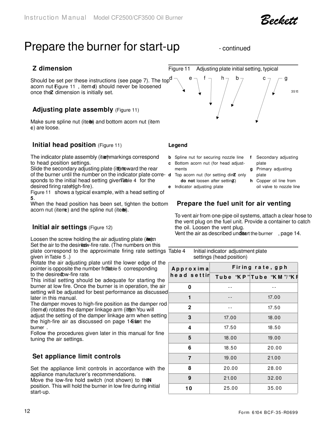
Should be set per these instructions (see page 7). The top acorn nut (Figure 11, item d) should never be loosened once the Z dimension is initially set.

Adjusting plate assembly (Figure 11)

Make sure spline nut (item b) and bottom acorn nut (item c) are loose.

Figure 11 – Adjusting plate initial setting, typical

d

e

f

h

b

c

g

3515

Initial head position (Figure 11)

The indicator plate assembly (item e) markings correspond to head position settings.

Slide the secondary adjusting plate (item f) toward the rear of the burner until the number on the indicator plate corre- sponds to the initial head setting given in Table 4 for the desired firing rate (high-fire).

Figure 11 shows a typical example, with a head setting of

5.

When the head position has been set, tighten the bottom acorn nut (item c) and the spline nut (item b).

Initial air settings (Figure 12)

Loosen the screw holding the air adjusting plate (item m). Set the air to the desired low-firerate. (The numbers on this plate correspond to the approximate firing rate settings given in Table 5.)

Rotate the air adjusting plate until the lower edge of the pointer is opposite the number from Table 5 corresponding to the desired low-fire rate.

This initial setting should be adequate for starting the burner at low fire. Once the burner is in operation, the air setting will be adjusted for best performance as discussed later in this manual.

The damper moves to high-fire position as the damper rod (item d) rotates the damper linkage arm (item f). You will adjust the setting of the damper linkage arm when setting the high-fire air as discussed on page 14 in Start the burner.

Follow the procedures given later in this manual for fine tuning the air settings.

Set appliance limit controls

Set the appliance limit controls in accordance with the appliance manufacturer's recommendations.

Move the low-fire hold switch (not shown) to the “IN” position. This will hold the burner in low fire during initial start-up.

Legend

b Spline nut for securing nozzle line

f

Secondary adjusting

c Bottom acorn nut (for head adjust-


plate

ments

g

Primary adjusting

d Top acorn nut (for setting dim. Z only


plate

do not loosen after setting Z)

h

Copper oil line from

e Indicator adjusting plate


oil valve to nozzle line

Prepare the fuel unit for air venting

To vent air from one-pipe oil systems, attach a clear hose to the vent plug on the fuel unit. Provide a container to catch the oil. Loosen the vent plug.

Vent the air as described under Start the burner, page 14.

Table 4 – Initial indicator adjustment plate settings (head position)

Approximate

Firing rate, gph

head settings

Tube “KP”

Tube “KM”/“KR”


0

--

--


1

--

17.00


2

--

17.50


3

17.00

18.00


4

17.50

18.50


5

18.00

19.00


6

18.50

20.00


7

19.00

21.00


8

20.00

28.00


9

21.00

32.00


10

25.00

35.00


12

Form 6104 BCF-35-R0699

Page 12
Image 12
Beckett CF 2500/ 3500 instruction manual Dimension, Adjusting plate assembly Figure, Initial head position Figure

CF 2500/ 3500 specifications

The Beckett CF 2500/3500 series represents a significant advancement in the oil burner technology, widely recognized for its high efficiency and reliability. These burners are designed for residential and light commercial applications, ensuring optimal heating performance with minimal environmental impact.

One of the standout features of the CF 2500 and 3500 models is their robust construction, which utilizes high-quality materials to enhance durability and longevity. This is particularly beneficial in demanding operational environments where the equipment may be subject to wear and tear. Both models are equipped with an advanced combustion head that promotes superior air-fuel mixing, leading to more efficient burning and lower emissions.

The combustion technology employed in these burners is centered around reliable ignition and stable flame management. The CF series features an innovative electronic control system that not only allows for precise control of the burner operation but also includes diagnostic capabilities. This ensures that maintenance can be performed efficiently, reducing downtime and service costs.

In terms of energy efficiency, the CF 2500/3500 models boast impressive ratings, making them ideal for homeowners looking to reduce energy bills while minimizing their carbon footprint. The burners can seamlessly integrate with various heating systems, providing flexibility in design and installation.

Another noteworthy characteristic is the user-friendly design, which simplifies the installation process. The compact size of the CF series allows it to fit into tight spaces while still delivering powerful performance. Moreover, the access panels for maintenance are strategically placed, enhancing technician efficiency during service calls.

Safety features are paramount in the Beckett CF series, which includes flame monitoring and flame failure response systems. These features ensure that the burner operates safely and effectively, thereby minimizing the risk of operational incidents.

In conclusion, the Beckett CF 2500 and 3500 oil burners are a blend of efficiency, ease of use, and safety. Their advanced technologies and features set a new standard in the oil burner market, making them a top choice for those seeking reliable and eco-friendly heating solutions. These units not only meet the demands of today's heating requirements but also set a path towards a more sustainable future.