POWERPLAY PRO HA4600
3
4
5
6
7
8
9
10
11
12
13
The
The HEADPHONE OUT socket is connected in parallel with the output sockets on the rear panel and provides an additional means of listening to the individual channels. This function is particularly useful when the equipment has been permanently installed in a rack.
A further input signal can be mixed in to the MAIN or the DIRECT
The L MUTE switch mutes the left input signal.
The R MUTE switch mutes the right input signal.
The MONO switch can be used to switch each of the amplifiers from stereo to mono operation.
The BASS control can be used to increase or decrease the lower frequencies
The TREBLE control can be used to increase or decrease the higher frequencies
The BALANCE control sets the ratio level between the MAIN or DIRECT IN signal and the input signal, which was applied to the AUX input.
The OUTPUT LEVEL control is used to set the sound level of each individual amplifier. At the same time it also controls the left and right channels.
The
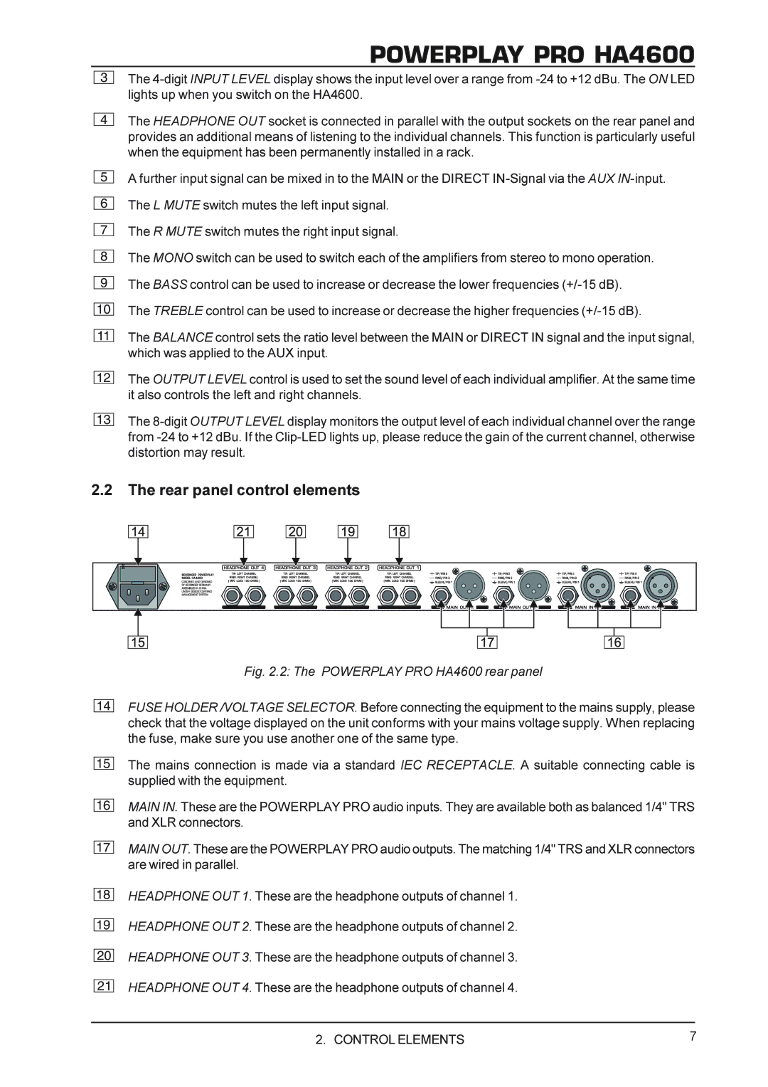
2.2The rear panel control elements
14
15
16
17
18
19
20
21
Fig. 2.2: The POWERPLAY PRO HA4600 rear panel
FUSE HOLDER /VOLTAGE SELECTOR. Before connecting the equipment to the mains supply, please check that the voltage displayed on the unit conforms with your mains voltage supply. When replacing the fuse, make sure you use another one of the same type.
The mains connection is made via a standard IEC RECEPTACLE. A suitable connecting cable is supplied with the equipment.
MAIN IN. These are the POWERPLAY PRO audio inputs. They are available both as balanced 1/4" TRS and XLR connectors.
MAIN OUT. These are the POWERPLAY PRO audio outputs. The matching 1/4" TRS and XLR connectors are wired in parallel.
HEADPHONE OUT 1. These are the headphone outputs of channel 1.
HEADPHONE OUT 2. These are the headphone outputs of channel 2.
HEADPHONE OUT 3. These are the headphone outputs of channel 3.
HEADPHONE OUT 4. These are the headphone outputs of channel 4.
2. CONTROL ELEMENTS | 7 |