9.Sometimes the burners will not ignite immediately and seem to ‘blow’ slightly when they do ignite. This usually due to air in the gas lines, which will clear itself within seconds.
10.If after following the instructions given, satisfactory performance cannot be obtained, contact the local gas authority for advice and assistance.
Electrical connection
The connection of the hobs to mains is effected via the flex and the three pin plug located underneath the hotplate. The appliance operate at a main voltage of 120V a.c., frequency 60Hz. Electric power absorption is about 1W.
WARNING: Electrical Grounding Instructions: This appliance is equipped with a
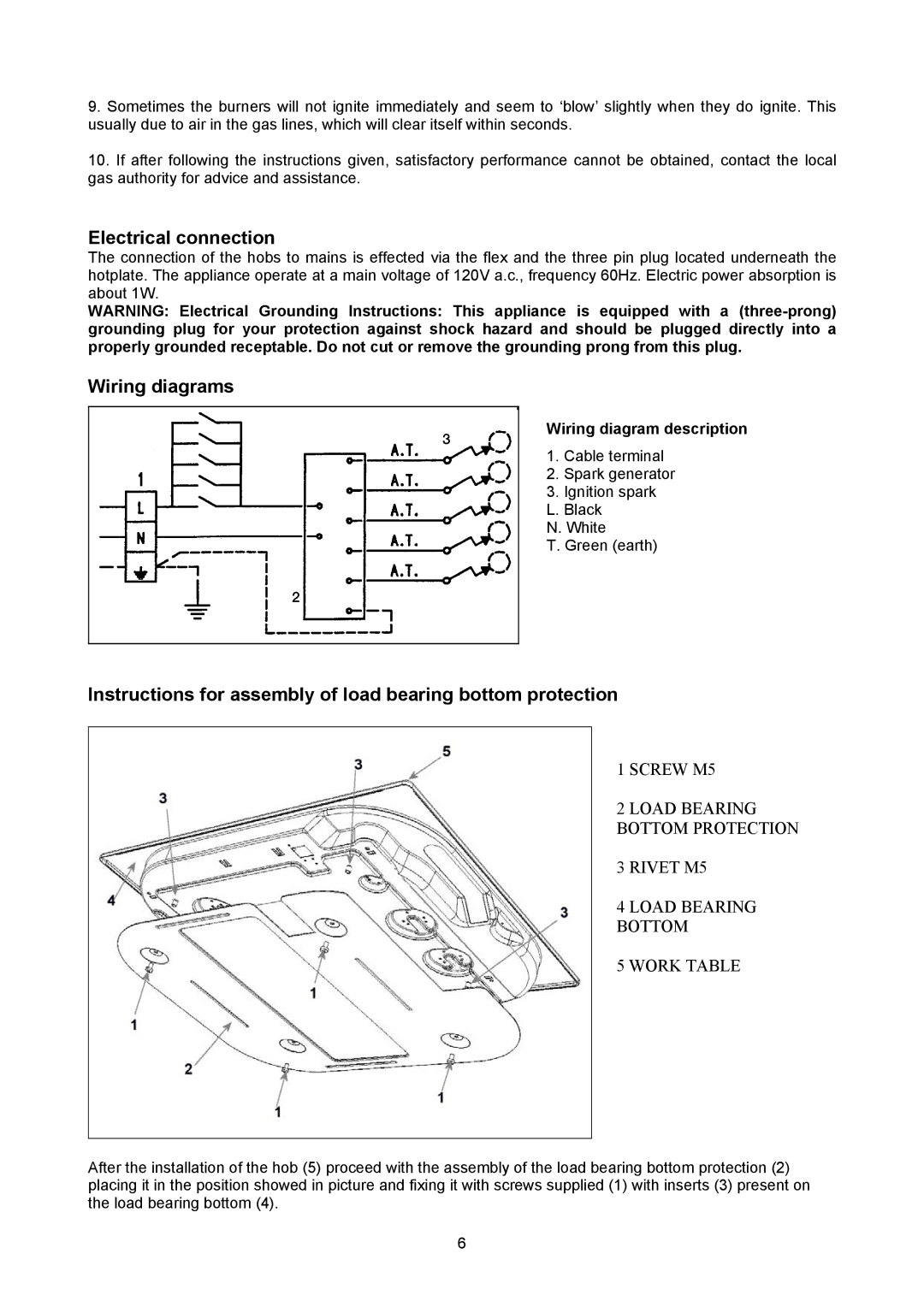
Wiring diagrams
Wiring diagram description
1. Cable terminal
2. Spark generator
3. Ignition spark L. Black
N. White
T. Green (earth)
Instructions for assembly of load bearing bottom protection
1 SCREW M5
2 LOAD BEARING BOTTOM PROTECTION
3 RIVET M5
4 LOAD BEARING BOTTOM
5 WORK TABLE
After the installation of the hob (5) proceed with the assembly of the load bearing bottom protection (2) placing it in the position showed in picture and fixing it with screws supplied (1) with inserts (3) present on the load bearing bottom (4).
6